-
[멀티프로세서] Multi-Processor Specification(MPS)프로젝트/운영체제 만들기 2023. 7. 18. 21:16
글의 참고
- 64-ia-32-architectures-software-developer-vol-3a-part-1-manual.pdf [Order Number: 253668-060US]
- MultiProcessor Specification 1.4
- https://en.wikipedia.org/wiki/MultiProcessor_Specification
글의 전제
- 밑줄로 작성된 글은 강조 표시를 의미한다.
- 그림 출처는 항시 그림 아래에 표시했다.
- 이 글은 `MultiProcessor Specification 1.4`를 기준으로 한다.
글의 내용
- 멀티 프로세서
: `멀티 프로세서` 스펙은 x86 기반의 다중 프로세서를 효율적으로 처리하기 위해 등장했다. MPS에서는 현재까지도 사용되고 있는APCI에 자세하게 설명되어 있다. 그러나, MPS는 지금은 거의 사용되지 않는다. PC 기반의 시장에서 멀티 프로세서에 관한 표준은 ACPI로 넘어온지 오래다. 여기서는 APIC의 초기 이론과 등장 배경에 대해 간단하게만 알아본다.
- 논리 프로세서
: 인텔에서 제시하는 `논리 프로세서`는 뭘까?
" 논리 프로세서 개수 : `물리 코어 개수 * 물리 코어 당 존재하는 스레드 개수`
: 코어에서 하나의 스레드만 지원한다면 논리 프로세서는 물리 프로세서와 동일한 의미가 될 것이다.
....
Some operating systems and software applications view the physical processor as logical processors. `A logical processor` is the number of the processor's cores multiplied by the number of threads per core. vCPUs are actually the amounts of of time a virtual machine gets on a logical processor. The number of cores and threads of an Intel processor can be found in the Intel's Technical Specifications website by searching by processor number.
....
- 참고 : https://www.intel.com/content/www/us/en/support/articles/000036898/processors/intel-xeon-processors.html- 시스템 아키텍처
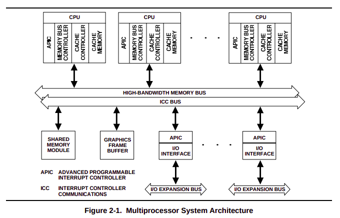
: 인텔 MP 스펙에서 제시하는 시스템 아키텍처는 다음과 같다.
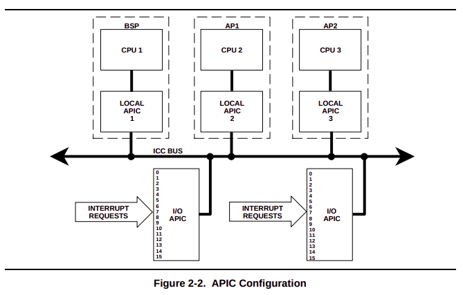
- BSP & AP
: 인텔 MP 스펙에서 빠질 수 없는 내용이 `BSP`와 `AP`에 대한 부분이다.
The MP initialization protocol defines two classes of processors: the bootstrap processor (BSP) and the application processors (APs). Following a power-up or RESET of an MP system, system hardware dynamically selects one of the processors on the system bus as the BSP. The remaining processors are designated as APs.
As part of the BSP selection mechanism, the BSP flag is set in the IA32_APIC_BASE MSR (see Figure 10-5) of the BSP, indicating that it is the BSP. This flag is cleared for all other processors.
The BSP executes the BIOS’s boot-strap code to configure the APIC environment, sets up system-wide data structures, and starts and initializes the APs. When the BSP and APs are initialized, the BSP then begins executing the operating-system initialization code.
Following a power-up or reset, the APs complete a minimal self-configuration, then wait for a startup signal (a SIPI message) from the BSP processor. Upon receiving a SIPI message, an AP executes the BIOS AP configuration code, which ends with the AP being placed in halt state.
For Intel 64 and IA-32 processors supporting Intel Hyper-Threading Technology, the MP initialization protocol treats each of the logical processors on the system bus or coherent link domain as a separate processor (with a unique APIC ID). During boot-up, one of the logical processors is selected as the BSP and the remainder of the logical processors are designated as APs.
- 참고 : 8.4.1 BSP and AP Processors
.....
Figure 2-2 gives a different point of view of a compliant system, showing the configuration of the APICs with respect to the CPUs. While all processors in a compliant system are functionally identical, this specification classifies them into two types: the bootstrap processor (BSP) and the application processors (AP). Which processor is the BSP is determined by the hardware or by the hardware in conjunction with the BIOS. This differentiation is for convenience and is in effect only during the initialization and shutdown processes. The BSP is responsible for initializing the system and for booting the operating system; APs are activated only after the operating system is up and running. CPU1 is designated as the BSP. CPU2, CPU3, and so on, are designated as the APs.
....
- 참고 : MPspec.pdf : 2.1.1 System Processors: 위의 내용을 요약하면 다음과 같다.
0" MP 스펙에 호환되는 구조에서 모든 프로세서들은 기능적으로 동일하다. 그러나 스펙에서는 편의를 위해 프로세서를 2가지 타입으로 구분한다
0.1" BSP : Bootstrap processor
0.2" AP : Application processor
1" 어떤 프로세서가 BSP 이냐는 하드웨어에 의해 결정된다. BSP와 AP라는 용어를 나누는 기준은 단순히 편의를 위해서다.
2" 초기화 과정과 종료 과정에서는 BSP만 동작한다.
3" BSP는 시스템의 부팅과 운영 체제의 부팅 과정을 담당한다. AP는 운영 체제가 모든 부팅 과정을 완료된 후에 활성화된다.: 인텔은 현재 아래와 같은 구조를 사용하고 있지 않다. 그러나, 현재 대부분의 시스템 아키텍처는 아래와 같이 `global interrupt controller(I/O APIC)`와 `local interrupt controller(Local APIC)`로 나눠져 있다.
- MP 시스템 메모리
: MP 스펙에서 I/O & Local APIC의 디폴트 베이스 메모리 어드레스는 각각 `0FEC0_0000h`, `0FEE0_0000h`다. 그리고, 메모리-맵 I/O 디바이스들은 메모리 상위 부분에 맵핑되어야 한다고 하는데, 이게 MP쪽 관련된 I/O 디바이스들만 그런것인지, 모든 인텔 호환 I/O 디바이스들이 그런 것 인지 확인이 필요하다.
The MP memory specifications are based on the standard PC/AT memory map, which currently has a physical memory space of four gigabytes, as shown in see Figure 3-1. Physical memory should begin at 0 and be contiguous. Memory-mapped I/O devices should be mapped at the top of physical memory. The APIC default base memory addresses defined by this specification are `0FEC0_0000h` and `0FEE0_0000h`.
- 참고 : 3.1 System Memory Configuration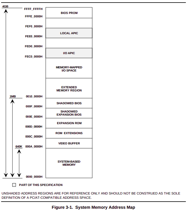
: 그리고 Local APIC 영역과 I/O APIC 영역에 접근할 때, 고려해야 할 부분이 있다. 메모리 맵에서 Local APIC 영역은 각 프로세서에 자신의 Local APIC에 접근하기 위해서 예약된 영역이다. 그리고 I/O APIC 영역은 모든 프로세서가 시스템에 존재하는 하나의 I/O APIC에 접근하기 위해 예약된 영역이다. 2개 모두 캐쉬는 불가능하다. 왜냐면, 쓰기가 빈번하게 발생할 수 있기 때문이다. 그리고 디바이스와의 통신 수단이 메모리를 통해서 진행하기 때문에 절대 해당 영역을 캐쉬하면 안된다.
The cacheability and shareability of the physical memory space are defined in Table 3-1. The address space reserved for the local APIC is used by each processor to access its own local APIC. The address space reserved for the I/O APIC must be shareable by all processors to permit dynamic reconfiguration.
- 참고 : MPspec.pdf: 시스템에 프로세서가 4개여도, 각 프로세서가 자신의 Local APIC를 설정하기 위해 접근하는 메모리-맵 주소는 모두 같다. 즉, `0FEE0_0000h`에 접근한다. 사실, 이 부분은 SW 개발자 입장에서는 보이지 않는 영역이다(동일한 주소에 접근하는데, 각 Local APIC를 설정할 수 있다는 부분이 말이다).
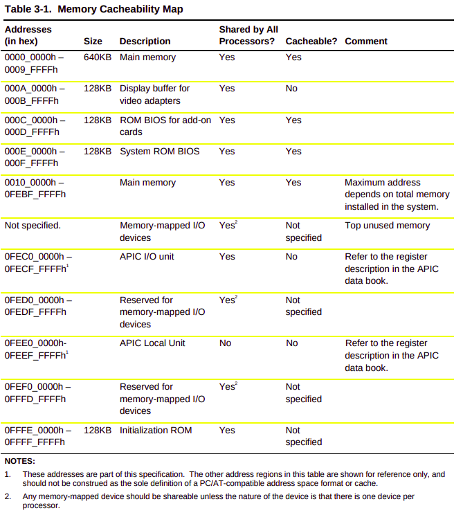
: 위에서 캐쉬가 가능한 영역은 `ROM`이라는 특징이 있다. 즉, 읽기만 가능한 영역을 의미한다.
- Local & I/O APIC
: 인텔 MP를 언급할 때, APIC는 절대로 빠질 수 가 없는 주제다.
....
The local APIC units also provide interprocessor interrupts (IPIs), which allow any processor to interrupt any other processor or set of processors. There are several types of IPIs. Among them, the `INIT IPI` and the `STARTUP IPI` are specifically designed for system startup and shutdown.
Each local APIC has a Local Unit ID Register and each I/O APIC has an I/O Unit ID Register. The ID serves as a physical name for each APIC unit. It is used by software to specify destination information for I/O interrupts and interprocessor interrupts, and is also used internally for accessing the ICC bus.
Due to the distributed architecture, the APIC local and I/O units can be implemented in either a single chip, such as Intel’s 82489DX interrupt controller, or they can be integrated with other parts of the system’s components. For example, the local APIC may be integrated with the CPU chip, such as `Intel’s Pentium processors (735\90, 815\100)`, and the I/O APIC may be integrated with the I/O chipset, such as `Intel’s 82430 PCI-EISA bridge chipset`.
....
- 참고 : MPspec.pdf : 2.1.2 Advanced Programmable Interrupt Controller: 위의 내용을 요약하면 다음과 같다.
0" LAPIC들 끼리는 인터럽트를 서로 주고 받을 수 있다. 이걸 `IPI`라고 한다. 대표적으로 `INIT IPI`와 `STARTUP IPI(SIPI)`가 존재하는데, `INIT IPI`를 받은 프로세서는 `wait for SIPI state` 상태가 만든다. 주로, AP가 BSP에 의해서 받게 된다. AP들은 `power-on reset`, `reset` 이후에도 `wait for SIPI state`가 된다. `SIPI`는 AP`s 들에게 전달되는 인터럽트로 SIPI 안에는 특정 `벡터 주소`가 들어있다. AP`s 들은 SIPI 안에 벡터 주소를 확인해서 글로 점프하게 된다[참고1].
1" 각각의 Local &I/O APIC는 자신만의 `Unit ID 레지스터`를 가지고 있다. ID를 통해 각각의 APIC를 구분할 수 가 있다.
2" APIC의 구조는 `distributed`과 `integrated` 가 있다. `distributed` 구조는 LAPIC가 CPU와 별개의 칩으로 존재한다(`Intel’s 82489DX`). 그러나, `integrated` 구조는 CPU와 LAPIC가 한 칩에 존재한다. `Intel’s Pentium processors (735\90, 815\100)` 같은 경우가 LAPIC와 CPU가 한 칩에 존재하게 된다. I/O APIC도 별도로 존재하는 경우도 있고, 한 칩에 함께 존재하는 경우도 있다. I/O APIC가 I/O chipset에 병합된 모델이 `Intel’s 82430 PCI-EISA bridge chipset` 이다......
The Intel Advanced Programmable Interrupt Controller (APIC) is based on a distributed architecture. Interrupt control functions are distributed between two basic functional units: the local unit and the I/O unit. The local and I/O units communicate through a bus called the ICC bus. The I/O unit senses an interrupt input, addresses it to a local unit, and sends it over the ICC bus. The local unit that is addressed accepts the message sent by the I/O unit.
In an MP-compliant system, one local APIC per CPU is required. Depending on the total number of interrupt lines in an MP system, one or more I/O APICs may be used. The bus interrupt line assignments can be implementation-specific and can be defined by the MP configuration table described in Chapter 4.
The Intel 82489DX APIC is a “discrete APIC” implementation. The programming interface of the 82489DX APIC units serves as the base of the MP specification. Each APIC has a version register that contains the version number of a specific APIC implementation. The version register of the 82489DX family has a version number of “0x,” where x is a four-bit hexadecimal number. Version number “1x” refers to Pentium processors with integrated APICs, such as the Pentium 735\90 and 815\100 processors, and x is a four-bit hexadecimal number.
The integrated APIC maintains the same programming interface as the 82489DX APIC. Table 3-2 describes the features specific to the integrated APIC.
.....
- 참고 : MPspec.pdf : 3.6 Multiprocessor Interrupt Control: 위의 내용을 요약하면 다음과 같다.
0" 인텔 APIC는 `분배 구조`를 가지고 있다. 여기서 분배 구조란 인터럽트를 분배한다는 뜻이다.
1" APIC에서 인터럽트는 2가지 요소에 의해 제어된다
1.1" Local APIC : I/O APIC로 부터 인터럽트를 전달받는다.
2.1" I/O APIC : 직접적으로 인터럽트 라인이 연결되어 있다. 그래서 인터럽트를 감지하고, 해당 인터럽트가 어떤 Local APIC 와 매핑되었는지를 검사한다. 그리고 ICC 버스를 통해 해당 인터럽트를 매핑된 Local APIC로 보낸다.
2" Local APIC 와 I/O APIC는 ICC 라는 버스를 통해 서로 통신한다.
3" MP 스펙과 호환되는 구조에서는 CPU 마다 Local APIC를 별도로 갖는다.
4" 전체 인터럽트 개수에 따라, 시스템에서 I/O APIC는 한 개일 수도 있고 여러 개 일 수도 있다.- MP Configuration Table
: MP에서 아래의 구조를 알고 있는 것은 굉장히 중요하다.
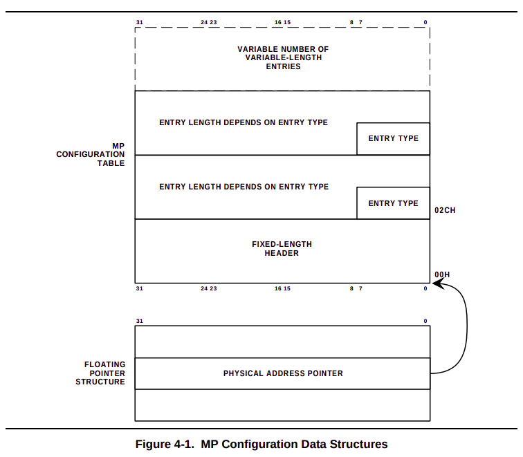
: 위의 그림을 요약하면 다음과 같다.
0" MP 스펙에서 정의된 3군데에서 `MP floating pointer structure` 을 찾는다.
1" `MP configuration table` 가 어디에 저장되어 있는지 알아야 한다. `MP floating pointer structure` 필드중 `PHYSICAL ADDRESS POINTER`는 `MP configuration table` 위치를 나타낸다.
2" `MP configuration table` 바로 뒤에 MP 엔트리들이 뒤따라 나온다. 이 엔트리들은 현재 시스템에 설정된 MP 정보를 가지고 있다.: `MP configuration table` 의 필드들을 모두 알면 좋겠지만, 여기서는 중요한 필드들만 짚고 넘어간다.
Field Offset (in bytes) Length (in bits) Description SIGNATURE 0 32 The ASCII string representation of “PCMP,” which confirms the presence of the table. BASE TABLE LENGTH 4 16 The length of the base configuration table in bytes, including the header, starting from offset 0. This field aids in calculation of the checksum. CHECKSUM 7 8 A checksum of the entire base configuration table. All bytes, including CHECKSUM and reserved bytes, must add up to zero ... ... ... ... ENTRY COUNT 34 16 The number of entries in the variable portion of the base table. This field helps the software identify the end of the table when stepping through the entries. ADDRESS OF LOCAL APIC 36 32 The base address by which each processor accesses its local APIC. : `MP configuration table`은 고정 길이의 `헤더 영역`와 동적 길이의 `엔트리 영역`으로 나뉜다. `엔트리 영역`은 시스템에 따라 사이즈가 달라진다. 그런데, 각 엔트리들은 모두 길이가 고정이다. 즉, 엔트리 영역이 사이즈가 동적인 이유는 엔트리들의 개수가 시스템에 따라 달라지기 때문이다. 각 엔트리의 길이는 모두 고정 길이다. OS는 시스템에 멀티 프로세서를 적용하기 위해 시스템에 `MP configuration table`에 등록되어 있는 모든 엔트리들을 탐색할 필요가 있다. 이 때, 시작 지점은 당연히 `MP configuration table` 헤더 끝 부분이 됬다. 탐색은 어디까지 해야 할까? `MP configuration table`의 `ENTRY COUNT` 필드가 있다. 그 값을 탐색의 종료 시점이라고 설정하면 된다.
: 각 엔트리들은 `엔트리 타입`을 통해서 구분된다. 아래는 `엔트리 타입`에 따른, 엔트리 정보들을 보여준다.
Entry Description Entry Type Code Length (in bytes) Comments Processor 0 20 One entry per processor. Bus 1 8 One entry per bus. I/O APIC 2 8 One entry per I/O APIC. I/O Interrupt Assignment 3 8 One entry per bus interrupt source. Local Interrupt Assignment 4 8 One entry per system interrupt source. - Application Processor Startup
: BSP가 기본적인 작업을 마무리하는 시점에 AP`s 들을 `start-up` 시켜야 한다. 이 때, BSP는 AP`s 들에게 `INIT IPI`를 전송한다. 그리고, AP`s가 `wait-for-SIPI` 상태가 되기를 기다려야 하므로, `10ms`를 기다린다. 그 후에 BSP는 `SIPI` 브로드캐스트해서 모든 AP`s 들을 `start-up` 시킨다.
BSP sends AP an INIT IPI
BSP DELAYs (10mSec)
If ( APIC_VERSION is not an 82489DX ) {
BSP sends AP a STARTUP IPI
BSP DELAYs (200µSEC)
BSP sends AP a STARTUP IPI
BSP DELAYs (200µSEC)
}
BSP verifies synchronization with executing AP
- 참고 : Example B-1. Universal Start-up Algorithm- INIT IPI
: `INIT IPI`를 받은 프로세서는 `RESET`이 되버린다. `INIT IPI`는 `BSP -> AP` 로만 전송하는 IPI가 아니다. 양방향으로 전송이 가능하다(BSP <-> AP). BSP 혹은 AP는 `INIT IPI`에 대한 동작이 `고정` 되어있다. 예를 들어, BSP로 설정된 코어는 `INIT IPI`를 받으면, BIOS 혹은 UEFI 를 실행하면서 시스템 초기화를 진행한다. 그러나, AP로 설정된 코어들이 `INIT IPI`를 받으면, 최소한의 초기화 작업을 한 뒤 `wait for SIPI state`가 된다.
INIT IPIs can be used with systems based on the 82489DX APIC, or on systems that are based on multiple Pentium (735/90, 815/100) processors. INIT IPI is an Interprocessor Interrupt with trigger mode set to level and delivery mode set to “101” (bits 8 to 10 of the ICR). INIT IPIs should always be programmed as level triggered; the operating system must perform two writes to the ICR to assert and then deassert this delivery mode.
An INIT IPI is an IPI that has its delivery mode set to RESET. Upon receiving an INIT IPI, a local APIC causes an INIT at its processor. The processor resets its state, except that caches, floating point unit, and write buffers are not cleared. Then the processor starts executing from a fixed location, which is the reset vector location. To cause the processor to jump to a different location, the INIT IPI must be used as part of a warm-reset.
The warm reset is a feature of every standard PC/AT BIOS. It allows the INIT signal to be asserted without actually causing the processor to run through its entire BIOS initialization procedure (POST). This feature is used, for example, to return an 80286 processor to Real Mode. The key components of warm reset are the following:
• Shutdown code. One of the first actions of the BIOS POST procedure is to read the shutdown code from location `0Fh` of the CMOS RAM. This code can have any of several values that indicate the reason that an INIT was performed. A value of `0Ah` indicates a `warm reset`.
• Warm-reset vector. When POST finds a shutdown code of 0Ah, it executes an indirect jump via the warm-reset vector, which is a doubleword pointer in system RAM location 40:67h.
By putting an appropriate pointer in the warm-reset vector, setting the shutdown code to 0Ah, then causing an INIT, the BIOS (or the operating system) can cause the current processor to jump immediately to any location. Because all processors in an MP system share the same system memory, and because the INIT IPI gives one processor the power to cause an INIT at another, the operating system can cause any processor to jump immediately to any location.
- 참고 : B.4.1 USING INIT IP: 위의 내용을 요약하면 다음과 같다.
0" `INIT IPI`는 트리거 모드는 `레벨 트리거`로 설정되어야 하며, `전송 모드`는 `101(INIT)`로 되어야 전송되는 인터럽트다. `INIT IPI`는 반드시 레벨 트리거 모드로 동작해야 한다고 설명한다. 레벨 트리거 이므로, SET 되면 그 신호는 계속 SET이고, CLEAR면 계속 CLEAR가 된다. 즉, 엣지 트리거와 같이 SET 됬다가 자동으로 CLEAR 되는 구조가 아니다. 그래서 ICR에 2번 `쓰기`를 해야한다고 말하고 있다. 즉, BSP는 `INIT IPI`를 한 번 전송(assert)한다. 그런데, 레벨 트리거 이므로, AP가 `INIT IPI`를 인식했으면, BSP는 CLEAR(deassert)를 해야한다고 한다.
1" `INIT IPI`는 `웜 리셋`과 동일한 기능으로 사용된다고 설명되고 있다. 즉, `INIT IPI`를 받은 프로세서는 캐쉬, 소수점 관련 하드웨어, write buffer를 제외하고 나머지 것들을 리셋한다.
2" PC/AT BIOS 기반의 PC가 `웜-리셋` 되면, BIOS는 POST 절차를 진행하지 않는다. 즉, BIOS는 제어권을 바로 OS에게 넘겨서 리얼 모드로 진입시킨다.- STARTUP IPI
: SIPI를 받은 프로세서는 리얼 모드로 돌아간다. 그리고, 리얼 모드에서 `000VV000h`로 점프하게 된다. 리얼 모드이기 때문에 1MB(100000h)로 주소를 지정해야 하기 때문에, `VV000h`로 나온 것이다. 여기에 4KB 정렬이므로, 뒤에 12비트는 0이다. SIPI의 벡터 주소를 지정할 때, 주의점이 있다. `0xA0 - 0xBF` 범위는 예약 영역이기 때문에, 이 범위의 벡터값은 사용해서는 안된다.
STARTUP IPIs are used with systems based on Intel processors with local APIC versions of 1.x or higher. These local APICs recognize the STARTUP IPI, which is an APIC Interprocessor Interrupt with trigger mode set to edge and delivery mode set to “110” (bits 8 through 10 of the ICR).
The STARTUP IPI causes the target processor to start executing in `Real Mode` from address `000VV000h`, where VV is an 8-bit vector that is part of the IPI message. Startup vectors are limited to a 4-kilobyte page boundary in the first megabyte of the address space. Vectors A0-BF are reserved; do not use vectors in this range. STARTUP IPIs are not maskable, do not cause any change of state in the target processor (except for the change to the instruction pointer), and can be issued only one time after RESET or after an INIT IPI reception or pin assertion. A STARTUP IPI neither requires the targeted APIC to be enabled nor the interrupt table to be programmed. If the target processor is in the halted state immediately after RESET or INIT, a STARTUP IPI causes it to leave that state and start executing. The effect is to set CS:IP to VV00:0000h.
For an operating system to use a STARTUP IPI to wake up an AP, the address of the AP initialization routine (or of a branch to that routine) must be in the form of 000VV000h. Sending a STARTUP IPI with VV as its vector causes the AP to jump immediately to and begin executing the operating system’s AP initialization routine.: `SIPI`를 받아 실행되는 프로세서의 CS:IP는 `VV00:0000`h이다. 리얼 모드에서는 `세그먼트 주소 << 4` 때문에 앞의 주소는 실제로 `VV000`과 같다.
- AP Shutdown Handling
: AP를 3가지 개체들에 의해 종료될 수 있다.
0" 자기 스스로 종료할 수 있다.
1" BSP에 의해 종료될 수 있다.
2" 또 다른 `active AP`에 의해 종료될 수 있다.: AP를 `active task` 및 `device driver`가 종료시킬 수는 없다. BSP를 종료시킬 수 있는 방법은 BSP 자기 자신 뿐이다. 즉, AP는 BSP를 종료시킬 수 없다. 그리고 `셧 다운` 과정에서 마지막에 종료되는 프로세서는 반드시 BSP 여야 한다. 즉, AP들이 모두 `셧 다운`되고 나서 BSP가 셧다운 되어야 한다.
An AP may be shut down by itself, by the BSP, or by another active AP. Shutting down an AP with an active task or a bound device driver is not permitted. Only the BSP may shut itself down, and it must be the last processor to shut down.
There are several possible alternatives for shutdown handling. Two of the possibilities are presented here by way of example.
In the simplest case, the operating system can define an IPI for shutting down and taking APs offline. The exact usage and behavior of an IPI that is defined for this purpose is operating system specific and is not defined in this specification.
Should the BSP need to take an AP off-line or to place the AP back into a HALT state, the BSP can also use the INIT IPI with Warm Restart. The operating system places the address of a HLT instruction in the warm-reset vector (40:67), sets the CMOS shut-down code to 0Ah, then sends an INIT IPI to the AP. The INIT IPI causes the AP to enter the BIOS POST routine, where it immediately jumps to the warm-reset vector and executes the operating system’s HLT instruction. Only one processor can execute the shutdown routine at any given time, due to the use of the shutdown code. The operating system must not rely on any code being executed after the delivery of an INIT IPI used to shut down an AP. As a result, the operating system must ensure that any required state information is captured and that caches are flushed as necessary before sending the INIT IPI.
In order to do a complete system shutdown, followed by a warm restart if necessary, the operating system should return the system to a state similar to that at `power-on`. This includes disabling the Local APIC interrupts (LINT0/LINT1/Local APIC Timer/Error interrupt) on all processors, disabling the Local APIC on all APs and disabling all interrupts at all the I/O APICs in the system. The operating system can use an IPI or an NMI to signal to all APs for per-processor shutdown handling. The operating system may then set the CMOS shutdown code to 0Ah and perform a keyboard controller reset.: 위에서는 AP 및 BSP를 종료시킬 수 있는 개체들에 알아봤다면, 이제는 실제 `셧 다운` 을 시키는 방법을 알아본다.
0" 첫 번째로 가장 간단한 방법은 운영 체제가 새롭게 `셧 다운` IPI를 새롭게 정의하는 것이다. 즉, AP`s 들을 셧다운 시킨 뒤, `off-line` 상태로 만드는 것이다. 이건 스펙에 명시되어 있는 방법이 아니다. 즉, 운영 체제에서 커스텀하라는 것이다.
1" 두 번째로 가장 보편적인 방법을 이용하는 것이다. 운영 체제는 `warm-reset vector` 지점에 `HLT` 명령어를 무한으로 실행하는 코드 주소로 설정하고, `CMOS shutdown code`를 0Ah로 설정하고, AP`s 들한테 `INIT IPI` 를 전송한다. 그러면, AP`s 들의 리셋 벡터가 HLT 명령어를 실행하는 곳으로 점프되기 때문에, BSP만이 시스템을 shutdown 시킬 수 있는 환경이 완성된다. 이제 BSP가 다른 프로세서의 방해없이 안전하게 시스템을 종료시킬 수 있는 환경이 된다.- MP 프로토콜
: `MP 초기화 프로토콜` 혹은 `MP 프로토콜`은 멀티 프로세서 아키텍처에서 여러 프로세서들을 초기화 및 동기화하기 위한 프로토콜이다. MP 프로토콜은 오직 `파워-업` 혹은 `리셋`에 의해서만 시작된다. 만약, MP 프로토콜이 모두 완료되고 어떤 프로세서가 BSP가 될지도 정해졌다면, 그 이후에 호출되는 모든 `INIT IPI`들에 대해서는 MP 프로토콜을 반복해서 실행하지 않는다. 대신에 모든 프로세서들은 자신의 `IA32_APIC_BASE MSR` 레지스터를 확인해서 자신이 BSP인지 AP인지를 확인한다. 그리고, BSP 라면 `BIOS boot-strap code`를 실행하고 AP라면 `wait-for-SPIP` 상태에서 대기한다.
The MP initialization protocol imposes the following requirements and restrictions on the system:
• The MP protocol is executed only after a power-up or RESET. If the MP protocol has completed and a BSP is chosen, subsequent INITs (either to a specific processor or system wide) do not cause the MP protocol to be repeated. Instead, each logical processor examines its BSP flag (in the IA32_APIC_BASE MSR) to determine whether it should execute the BIOS boot-strap code (if it is the BSP) or enter a wait-for-SIPI state (if it is an AP).
• All devices in the system that are capable of delivering interrupts to the processors must be inhibited from doing so for the duration of the MP initialization protocol. The time during which interrupts must be inhibited includes the window between when the BSP issues an INIT-SIPI-SIPI sequence to an AP and when the AP responds to the last SIPI in the sequence.
- 참고 : 8.4.2 MP Initialization Protocol Requirements and Restrictions- LAPIC after reset
: `xv6`에서 조금 독특한 방식으로 멀티 프로세서(AP`s)를 초기화한다. 아래는 `power-up` 혹은 `reset` 후에 프로세서의 레지스터 상태를 나타낸다.
Following a power-up or reset of the processor, the state of local APIC and its registers are as follows:
• The following registers are reset to all 0s:
•The DFR register is reset to all 1s.• IRR, ISR, TMR, ICR, LDR, and TPR
• Timer initial count and timer current count registers
• Divide configuration register
• The LVT register is reset to 0s except for the mask bits; these are set to 1s.
• The local APIC version register is not affected.
• The local APIC ID register is set to a unique APIC ID. (Pentium and P6 family processors only). The Arb ID register is set to the value in the APIC ID register.
• The spurious-interrupt vector register is initialized to 000000FFH. By setting bit 8 to 0, software disables the local APIC.
• If the processor is the only processor in the system or it is the BSP in an MP system (see Section 8.4.1, “BSP and AP Processors”); the local APIC will respond normally to INIT and NMI messages, to INIT# signals and to STPCLK# signals. If the processor is in an MP system and has been designated as an AP; the local APIC will respond the same as for the BSP. In addition, it will respond to SIPI messages. For P6 family processors only, an AP will not respond to a STPCLK# signal.
- 참고 : 10.4.7.1 Local APIC State After Power-Up or Reset
....
An INIT reset of the processor can be initiated in either of two ways:
• By asserting the processor’s INIT# pin.
• By sending the processor an INIT IPI (an IPI with the delivery mode set to INIT).
Upon receiving an INIT through either of these mechanisms, the processor responds by beginning the initialization process of the processor core and the local APIC. The state of the local APIC following an INIT reset is the same as it is after a power-up or hardware reset, except that the APIC ID and arbitration ID registers are not affected. This state is also referred to at the “wait-for-SIPI” state (see also: Section 8.4.2, “MP Initialization Protocol Requirements and Restrictions”).
- 참고 : 10.4.7.3 Local APIC State After an INIT Reset (“Wait-for-SIPI” State)
....
Only the Pentium and P6 family processors support the INIT-deassert IPI. An INIT-deassert IPI has no affect on the state of the APIC, other than to reload the arbitration ID register with the value in the APIC ID register.
- 참고 : 10.4.7.4 Local APIC State After It Receives an INIT-Deassert IPI: `INIT IPI`를 받은 프로세서는 `초기화 프로세스`를 진행하게 된다. 이 때, LAPCI의 상태는 `power-up` 및 `hardware reset`를 받은 후와 동일한 상태가 된다. 그러나, 다른 점이 존재한다. `power-up` 및 `hardware reset`은 전원을 Off/On 하기 때문에, `LAPIC ID register 및 arbitration ID register` 또한 리셋된다. 그러나, `INIT IPI`는 `software reset` 과 동일한 역할을 하기 때문에 전원을 Off/On 하지 않는다. 그러므로, 앞에 언급한 레지스터들의 상태가 그대로 유지된다. 이 때, 상태를 `wait-for-SIPI` 상태라고 한다.
- APIC Bus Arbitration
: Local APIC와 I/O APIC는 `System Bus` 및 `APIC Bus` 위에서 메시지를 전송해서 각 프로세서가 서로 통신할 수 있거나, 인터럽트를 주고 받을 수 있다. 그런데, 버스위에 여러 개의 메시지가 존재할 때, 이 메시지들을 어떤 순서로 전달할지는 버스가 중재한다. 펜티엄 4 및 제온 프로세서에서는 하드웨어 레벨에서 알아서 처리된다. 즉, 소프트웨어에게는 보이지 않는다(Trasnparent or Hidden).
: 펜티엄 6 패밀리 계열에서는 Local APIC는 `중재 우선순위`를 할당받게 된다. 중재 우선순위는 값이 클수록 높다. I/O APIC는 중재 우선순위를 통해서 현재 APIC Bus에 접근할 Local APIC를 선택한다. 즉, 중재 우선순위가 높은 Local APIC가 APIC Bus에 우선 접근하도록 한다. 여기서 APIC 버스를 점유한 Local APIC는 인터럽트 처리가 끝나면 중재 우선순위가 0으로 내려간다. 그리고 APIC 버스 점유에 실패한 Local APIC 들의 중재 우선순위는 1씩 증가한다.
When several local APICs and the I/O APIC are sending IPI and interrupt messages on the system bus (or APIC bus), the order in which the messages are sent and handled is determined through bus arbitration.
For the Pentium 4 and Intel Xeon processors, the local and I/O APICs use the arbitration mechanism defined for the system bus to determine the order in which IPIs are handled. This mechanism is non-architectural and cannot be controlled by software.
For the P6 family and Pentium processors, the local and I/O APICs use an APIC-based arbitration mechanism to determine the order in which IPIs are handled. Here, each local APIC is given an arbitration priority of from 0 to 15, which the I/O APIC uses during arbitration to determine which local APIC should be given access to the APIC bus. The local APIC with the highest arbitration priority always wins bus access. Upon completion of an arbitration round, the winning local APIC lowers its arbitration priority to 0 and the losing local APICs each raise theirs by 1.
The current arbitration priority for a local APIC is stored in a 4-bit, `software-transparent arbitration ID (Arb ID) register`. During reset, this register is initialized to the APIC ID number (stored in the local APIC ID register). The INIT level-deassert IPI, which is issued with and ICR command, can be used to resynchronize the arbitration priorities of the local APICs by resetting Arb ID register of each agent to its current APIC ID value. (The Pentium 4 and Intel Xeon processors do not implement the Arb ID register.)
Section 10.10, “APIC Bus Message Passing Mechanism and Protocol (P6 Family, Pentium Processors),” describes the APIC bus arbitration protocols and bus message formats, while Section 10.6.1, “Interrupt Command Register (ICR),” describes the INIT level de-assert IPI message.
Note that except for the SIPI IPI (see Section 10.6.1, “Interrupt Command Register (ICR)”), all bus messages that fail to be delivered to their specified destination or destinations are automatically retried. Software should avoid situations in which IPIs are sent to disabled or nonexistent local APICs, causing the messages to be resent repeatedly. Additionally, interrupt sources that target the APIC should be masked or changed to no longer target the APIC.
- 참고 : 10.7 SYSTEM AND APIC BUS ARBITRATION: 펜티엄 4 및 제온 프로세서에서는 `Arb ID` 레지스터를 사용하지 않는다. 펜티엄 6 계열 프로세서에서 `INIT level-deassert IPI`를 사용할 경우, `Arb ID` 레지스터를 Local APIC ID로 오버라이드한다. 즉, 2개의 레지스터의 값이 동일해진다. `xv6`가 이 과정을 진행한다.
: IPI 관련 주의점이 있다. `SIPI IPI`를 제외하고, 모든 IPI는 기본적으로 목적지에 전송이 실패하면, 자동으로 `리-트라이`를 시도한다. 좋아보이지만, 이게 만약 존재하지 않거나 비활성화된 Local APIC로 전송될 경우, 무한루프에 빠지는 문제가 생길 수 있다.
'프로젝트 > 운영체제 만들기' 카테고리의 다른 글
[xv6] Local APIC (0) 2023.07.21 [컴퓨터 구조] Local APIC (0) 2023.07.19 [xv6] Scheduling (0) 2023.07.17 [xv6] Spinlock (0) 2023.07.17 AT & T 문법 (0) 2023.07.15