-
[컴퓨터 구조] Local APIC프로젝트/운영체제 만들기 2023. 7. 19. 18:40
글의 참고
- 64-ia-32-architectures-software-developer-vol-3a-part-1-manual.pdf
글의 전제
- 밑줄로 작성된 글은 강조 표시를 의미한다.
- 그림 출처는 항시 그림 아래에 표시했다.
글의 내용
- Local & I/O APIC
....
External interrupts are received through pins on the processor or through the local APIC. The primary interrupt pins on Pentium 4, Intel Xeon, P6 family, and Pentium processors are the LINT[1:0] pins, which are connected to the local APIC (see Chapter 10, “Advanced Programmable Interrupt Controller (APIC)”). When the local APIC is enabled, the `LINT[1:0] pins` can be programmed through the `APIC’s local vector table (LVT)` to be associated with any of the processor’s exception or interrupt vectors.
When the local APIC is global/hardware disabled, these pins are configured as `INTR` and `NMI` pins, respectively. Asserting the INTR pin signals the processor that an external interrupt has occurred. The processor reads from the system bus the interrupt vector number provided by an external interrupt controller, such as an 8259A (see Section 6.2, “Exception and Interrupt Vectors”). Asserting the NMI pin signals a non-maskable interrupt (NMI), which is assigned to interrupt vector 2.
....
The processor’s local APIC is normally connected to a system-based I/O APIC. Here, external interrupts received at the I/O APIC’s pins can be directed to the local APIC through the system bus (Pentium 4, Intel Core Duo, Intel Core 2, Intel® Atom™, and Intel Xeon processors) or the APIC serial bus (P6 family and Pentium processors). The I/O APIC determines the vector number of the interrupt and sends this number to the local APIC. When a system contains multiple processors, processors can also send interrupts to one another by means of the system bus (Pentium 4, Intel Core Duo, Intel Core 2, Intel Atom, and Intel Xeon processors) or the APIC serial bus (P6 family and Pentium processors).
The LINT[1:0] pins are not available on the Intel486 processor and earlier Pentium processors that do not contain an on-chip local APIC. These processors have dedicated NMI and INTR pins. With these processors, external interrupts are typically generated by a system-based interrupt controller (8259A), with the interrupts being signaled through the INTR pin.
- 참고 : 64-ia-32-architectures-software-developer-vol-3a-part-1-manual.pdf - 6.3.1 External Interrupts: 위의 내용을 요약하면 다음과 같다
0" 위에 언급된 몇몇 인텔 프로세서에는 LINT[1:0] 이라는 `primary interrupt` pin 2개가 있다. 이 핀들은 Local APIC와 연결되어 있는데, Local APIC가 활성화(Enabled)될 경우, `LINT[1:0]` 핀은 APIC`s Local Vector Table(LVT)에 명시된 대로 동작하게 된다.
1" 만약, Local APIC가 `전역적으로` 비활성화 되어 있을 경우, `LINT[1:0]` 핀은 각각 `INTR(LINT0)]`과 `NMI(LINT1)`로 대응된다. `INTR`은 초기에 PIC에서 CPU에게 외부 인터럽트가 발생했다는 것을 알리기 위해 사용하던 핀이다. 이 말은, 이전 PIC 기반으로 동작했던 프로세서들과 동일하게 동작한다는 의미다.
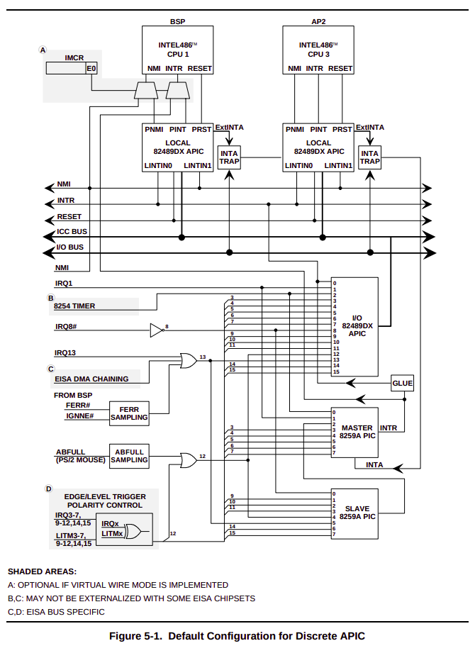
2" 486 및 초기 펜티엄 프로세서에는 Local APIC가 프로세서 온 칩이 아니었다. 그래서 프로세서 자체에 `NMI`와 `INTR`핀이 Local APIC와는 별도로 존재했다. 그래서 8259A로부터 외부 인터럽트를 다이렉트로 받는 구조였다.: 아래는 `486` 및 펜티엄 초기 버전의 APIC의 구조를 보여준다. 프로세서에 별도로 `NMI`와 `INTR`이 존재하는 것을 확인할 수 있다. `2` 번에서 말하고자 하는 내용은 Local APIC가 활성화 되어있어도 486 및 초기 펜티엄은 `LINT[1:0]`을 사용할 수 없다는 뜻이다.
....
The local APIC performs two primary functions for the processor:
• It receives interrupts from the processor’s interrupt pins, from `internal sources(?)` and from an external I/O APIC (or other external interrupt controller). It sends these to the processor core for handling.
• In multiple processor (MP) systems, it sends and receives interprocessor interrupt (IPI) messages to and from other logical processors on the system bus. IPI messages can be used to distribute interrupts among the processors in the system or to execute system wide functions (such as, booting up processors or distributing work among a group of processors).
....
The external I/O APIC is part of Intel’s system chip set. Its primary function is to receive external interrupt events from the system and its associated I/O devices and relay them to the local APIC as interrupt messages. In MP systems, the I/O APIC also provides a mechanism for distributing external interrupts to the local APICs of selected processors or groups of processors on the system bus.
....
When a local APIC has sent an interrupt to its processor core for handling, the processor uses the interrupt and exception handling mechanism described in Chapter 6, “Interrupt and Exception Handling.” See Section 6.1, “Interrupt and Exception Overview,” for an introduction to interrupt and exception handling.
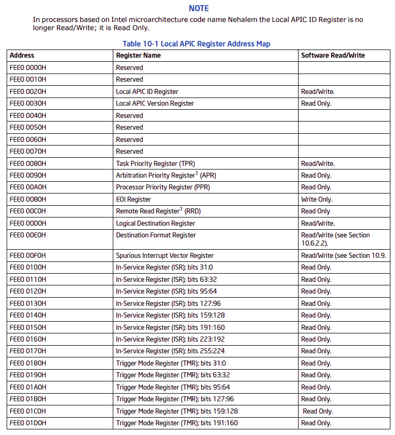
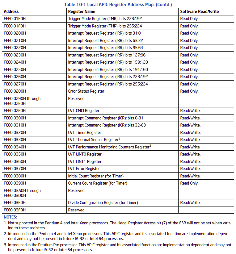
Each local APIC consists of a set of APIC registers (see Table 10-1) and associated hardware that control the delivery of interrupts to the processor core and the generation of IPI messages. The APIC registers are memory mapped and can be read and written to using the MOV instruction.
....
- 참고 :
64-ia-32-architectures-software-developer-vol-3a-part-1-manual.pdf - 10.1 Local and I/O APIC Overview: 위의 내용을 요약하면 다음과 같다
0" Local APIC는 2가지 핵심적인 기능을 담당한다.
0.1" 인터럽트 분배 : 여러 요소들로부터 인터럽트를 받아서 프로세서에게 전달한다.
0.2" IPI : 인터럽트 로드 밸런싱
1" I/O APIC는 프로세서 온 칩이 아닌, 시스템 온 칩이다. 주요 기능은 외부 인터럽트들을 받아서 Local APIC로 전달한다.
2" Local APIC의 인터럽트 및 익셉션 처리 메커니즘 또한 `Chapter 6` 에서 설명한 `인터럽트 및 익셉션 핸들링`과 동일하다.
3" 각 Local APIC는 자신만의 APIC 레지스터를 가지고 있다. 메모리 맵 방식을 사용하기 때문에, 간단하게 `MOV` 명령어만으로 통신이 가능하다.: 그런데, `local interrupt sources`가 뭘까? 외부 인터럽트를 제외한 나머지 인터럽트를 `내부 인터럽트 요소`라고 봐도 무방하다.
....
the processor’s LINT0 and LINT1 pins, the APIC timer, the performance-monitoring counters, the thermal sensor, and the internal APIC error detector are referred to as `local interrupt sources`.
....
- 참고 :
64-ia-32-architectures-software-developer-vol-3a-part-1-manual.pdf : 10.1 Local and I/O APIC Overview: 프로세서가 하나라고 가정했을 때, 어떻게 Local & I/O APIC가 구성되는지 알아보자.
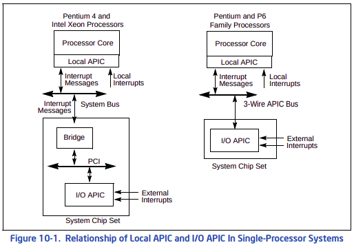
: 인텔 마이크로아키텍처에 따라 `버스 구조`가 조금 바꼈다. 쉽게 설명하면, 오른쪽이 레거시고 왼쪽이 최신 구조다. 차이는 다음과 같다.
왼쪽" Local APIC와 I/O APIC가 `시스템 버스`로 통신을 한다. 이 구조에서 Local APIC 구조를 `xAPIC 아키텍처`라고 부르는 것 같다.
오른쪽" Local APIC와 I/O APIC가 `APIC 버스(3-wire)`로 통신을 한다.: 아직 정확한 내용은 파악이 되지 않았지만, 추측해보면 인텔 펜티엄 4 혹은 제온 이상의 마이크로아키텍처에서는 PCI 디바이스로 I/O APIC를 등록하고 PCI 인터럽트인 MSI 방식을 이용해서 인터럽트를 발생시키는 것 같다. 그리고 FSB를 3-Wire APIC Bus가 아닌, 프로세서 시스템 버스를 이용하면서 퍼포먼스에 신경을 쓴 것 같다.
....
Individual pins on the I/O APIC can be programmed to generate a specific interrupt vector when asserted. The I/O APIC also has a “virtual wire mode” that allows it to communicate with a standard 8259A-style external interrupt controller. Note that the local APIC can be disabled (see Section 10.4.3, “Enabling or Disabling the Local APIC”). This allows an associated processor core to receive interrupts directly from an 8259A interrupt controller.
....
-: I/O APIC에 달려있는 인터럽트 라인들은 개별적으로 프로그래밍이 가능하다. 즉, 커스텀 인터럽트를 생성할 수가 있다. 그리고 `virtual wire mode`를 사용하면, 기존에 존재했던 ISA 기반의 `8259A PIC`에서 인터럽트를 I/O APIC가 그대로 받도록 할 수 있다. 즉, `virtual wire mode` 모드는 8259A와 호환성을 유지하기 위해 사용되는 모드다. 주의할 점은 이 때, 반드시 Local APIC는 비활성화 되어야 한다.
....
Figure 10-4 gives a functional block diagram for the local APIC. Software interacts with the local APIC by reading and writing its registers. APIC registers are memory-mapped to a 4-KByte region of the processor’s physical address space with an initial starting address of FEE00000H. For correct APIC operation, this address space must be mapped to an area of memory that has been designated as strong uncacheable (UC). See Section 11.3, “Methods of Caching Available.”
In MP system configurations, the APIC registers for Intel 64 or IA-32 processors on the system bus are initially mapped to the same 4-KByte region of the physical address space. Software has the option of changing initial mapping to a different 4-KByte region for all the local APICs or of mapping the APIC registers for each local APIC to its own 4-KByte region. Section 10.4.5, “Relocating the Local APIC Registers,” describes how to relocate the base address for APIC registers.
On processors supporting x2APIC architecture (indicated by CPUID.01H:ECX[21] = 1), the local APIC supports operation both in xAPIC mode and (if enabled by software) in x2APIC mode. x2APIC mode provides extended processor addressability (see Section 10.12).
....
- 참고 : 64-ia-32-architectures-software-developer-vol-3a-part-1-manual.pdf : 10.4.1 The Local APIC Block Diagram: 위의 내용을 요약하면 다음과 같다.
0" 소프트웨어(운영 체제 및 시스템 펌웨어)가 Local APIC와 통신하기 위해서는 Local APIC의 레지스터에 읽기 및 쓰기 동작을 통해서 통신해야한다. 즉, I/O 포트를 이용하는 것이 아닌, 메모리 맵 방식을 이용한다.
1" Local APIC의 메모리 맵 시작 주소는 프로세서의 물리 주소는 FEE00000h에 위치한다. 크기는 4KB를 차지한다. 정확히 4KB를 차지하므로, 코딩할 때, 패딩 및 정렬에 주의하자.
2" 이 영역은 `strong uncacheable`이기 때문에 코딩시에 `volatile` 키워드를 반드시 사용해야 한다.- Local APIC 레지스터
- Local APIC 존재 여부
: 이 글을 참고하자.
- Local APIC 활성화
: Local APIC를 활성화하는 먼저 `IA32_APIC_BASE_MSR`에서 11번째 비트를 SET 해야 한다.
1. Using the APIC global enable/disable flag in the `IA32_APIC_BASE MSR` (MSR address `1BH`; see Figure 10-5):
— When IA32_APIC_BASE[11] is 0, the processor is functionally equivalent to an IA-32 processor without an on-chip APIC. The CPUID feature flag for the APIC (see Section 10.4.2, “Presence of the Local APIC”) is also set to 0.
— When IA32_APIC_BASE[11] is set to 0, processor APICs based on the 3-wire APIC bus cannot be generally re-enabled until a system hardware reset. The 3-wire bus loses track of arbitration that would be necessary for complete re-enabling. Certain APIC functionality can be enabled (for example: performance and thermal monitoring interrupt generation).
.....
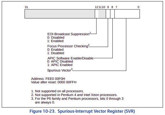
2. Using the APIC software enable/disable flag in the `spurious-interrupt vector register` (see Figure 10-23):
— If IA32_APIC_BASE[11] is 1, software can temporarily disable a local APIC at any time by clearing the APIC software enable/disable flag in the spurious-interrupt vector register (see Figure 10-23). The state of the local APIC when in this software-disabled state is described in Section 10.4.7.2, “Local APIC State After It Has Been Software Disabled.”
— When the local APIC is in the software-disabled state, it can be re-enabled at any time by setting the APIC software enable/disable flag to 1.
.....
- 참고 : 10.4.3 Enabling or Disabling the Local APIC: 위의 내용을 요약하면 다음과 같다.
0" `IA32_APIC_BASE_MSR`에서 11번째 비트가 0이면, 프로세서는 기능적으로 Local APIC가 없는 프로세서와 동일한 프로세서가 된다. 즉, PIC로 동작했던 이전 프로세서들과 동일하다는 뜻이다.
1" 런타임에 APIC를 비활성화하기 위해 `IA32_APIC_BASE_MSR`에서 11번째 비트를 CLEAR하면, 시스템이 하드웨어 리셋되기 전까지는 Local APIC들이 다시 활성화되지 않는다.
2" APIC 소프트웨어를 통해서 `spurious-interrupt vector register`의 8번째 비트를 CELAR 하면 특정 프로세서의 Local APIC를 일시적으로 비활성화 할 수 있다. 즉, `IA32_APIC_BASE_MSR`가 전체 LAPIC를 컨트롤하는 것과 달리, `spurious-interrupt vector register`는 개별 LAPIC를 즉각적으로 On/Off 할 수 있다. 그리고 이 방식은 `IA32_APIC_BASE_MSR` 와는 다르게 Local APIC의 On/Off 가 즉각적으로 이루어 진다.
3" `spurious-interrupt vector register`를 통해 LAPIC를 On/Off 하는 것은 `IA32_APIC_BASE_MSR`에서 11번째 비트가 SET 일 때나 의미가 있다. LAPIC가 전부 비활성화 되어 있는데, 개별적으로 활성화/비활성화 하는것이 무슨 의미가 있을까? 정리하자면, `IA32_APIC_BASE_MSR`은 시스템 전역적인 Local APIC를 컨트롤한다. 그리고 디테일하게 특정 프로세서의 Local APIC를 컨트롤 하고 싶다면, `spurious-interrupt vector register`를 이용하면 된다.: 아래는 `IA32_APIC_BASE_MSR`의 포맷이다.
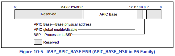
: 위 그림은 `IA32_APIC_BASE_MSR`의 필드들에 대한 설명이다. `APIC BASE` 필드는 Local APIC의 메모리 맵 베이스 주소를 알려준다. 그런데, `MP Configuration Table` 에서도 Local APIC의 베이스 어드레스를 알려준다. 둘은 동일한 값이다. 그런데, 차이가 있다면, `IA32_APIC_BASE_MSR` 의 APIC_BASE 필드는 `쓰기`가 가능한 필드다. 즉, Local APIC의 베이스 어드레스를 변경할 수 있다는 뜻이다. 이건 조금 있다 알아보도록 한다.
: `BSP` 필드는 자신이 BSP 인지를 알려준다. 이 필드를 읽었을 때, 1이면 해당 프로세서가 BSP라고 보면 된다. 0이면, AP다.
: `APIC Global Enable` 필드는 위에서 말했다시피, 시스템에 존재하는 모든 Local APIC를 컨트롤하는 용도로 사용된다.
The status and location of the local APIC are contained in the `IA32_APIC_BASE MSR` (see Figure 10-5). MSR bit functions are described below:
• BSP flag, bit 8 ⎯ Indicates if the processor is the bootstrap processor (BSP). See Section 8.4, “MultipleProcessor (MP) Initialization.” Following a power-up or reset, this flag is set to 1 for the processor selected as the BSP and set to 0 for the remaining processors (APs).
• APIC `Global` Enable flag, bit 11 ⎯ Enables or disables the local APIC (see Section 10.4.3, “Enabling or Disabling the Local APIC”). This flag is available in the Pentium 4, Intel Xeon, and P6 family processors. It is not guaranteed to be available or available at the same location in future Intel 64 or IA-32 processors.
• APIC Base field, bits 12 through 35 ⎯ Specifies the base address of the APIC registers. This 24-bit value is extended by 12 bits at the low end to form the base address. This automatically aligns the address on a 4-KByte boundary. Following a power-up or reset, the field is set to FEE0 0000H.
• Bits 0 through 7, bits 9 and 10, and bits MAXPHYADDR1 through 63 in the IA32_APIC_BASE MSR are reserved.
.....
- 참고 : 10.4.4 Local APIC Status and Location: 스펙에서는 `IA32_APIC_BASE_MSR`에서 `APIC BASE` 필드를 바꿈으로써, APIC 레지스터의 베이스 어드레스르 바꿀 수 있다고 말하고 있다. 그런데, 왜 이 필드는 24비트일까? Local APIC는 4KB(2^12) 정렬 되어야 하기 때문이다. 즉, 하위 12비트는 무조건 0 이다.
The Pentium 4, Intel Xeon, and P6 family processors permit the starting address of the APIC registers to be relocated from FEE00000H to another physical address by `modifying the value in the 24-bit base address` field of the IA32_APIC_BASE MSR. This extension of the APIC architecture is provided to help resolve conflicts with memory maps of existing systems and to allow individual processors in an MP system to map their APIC registers to different locations in physical memory.
- 참고 : 10.4.5 Relocating the Local APIC Registers: `Spurious-Interrupt Vector Register`에서 8번 비트를 통해 즉각적으로 개별 LAPIC를 `활성/비활성` 할 수 있다. 그리고 주목할 부분은 이 레지스터는 리셋후에 초기값이 `0x0000_00FF`이다. 즉, 8번째 비트가 `0`이다. 결국, 리셋후에는 LAPIC가 비활성화 되어 있단 소리다.
- Local APIC ID
: `LAPIC ID`는 멀티 프로세서 스케줄링시에 굉장히 중요한 개념이다. 왜냐면, 이 값을 기준으로 각 프로세서를 구분하기 때문이다(각 LAPIC와 CPU 코어는 1:1 대응된다). `xAPIC 모드`에서는 MSB 8비트만 읽으면 된다. 팬티엄 6 시리즈건 제온 이건 상관없이, `xAPIC Mode`에서는 MSB 8비트면 LAPIC를 구분할 수 있다.

- Local APIC 타이머
: Local APIC는 각각의 APIC 타이머를 가지고 있다. 이 타이머를 설정하기 위해서는 4개의 레지스터를 설정해야 한다.
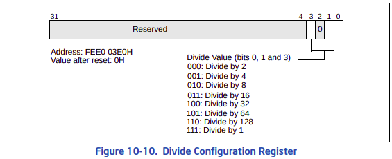
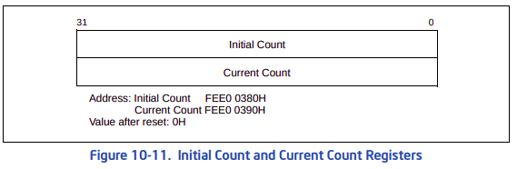
The local APIC unit contains a 32-bit programmable timer that is available to software to time events or operations. This timer is set up by programming four registers: the `divide configuration register` (see Figure 10-10), the `initial count` and `current-count registers` (see Figure 10-11), and the `LVT timer register` (see Figure 10-8).
....
The APIC timer frequency will be the processor’s bus clock or core crystal clock frequency (when TSC/core crystal clock ratio is enumerated in `CPUID leaf 0x15`) divided by the value specified in the divide configuration register.
The timer can be configured through the timer LVT entry for one-shot or periodic operation. `In one-shot mode`, the timer is started by programming its initial-count register. The initial count value is then copied into the current count register and count-down begins. After the timer reaches zero, an timer interrupt is generated and the timer remains at its 0 value until reprogrammed.
`In periodic mode`, the current-count register is automatically reloaded from the initial-count register when the count reaches 0 and a timer interrupt is generated, and the count-down is repeated. If during the count-down process the initial-count register is set, counting will restart, using the new initial-count value. The initial-count register is a read-write register; the current-count register is read only.
A `write of 0 to the initial-count register effectively stops the local APIC timer`, in both one-shot and periodic mode.
The LVT timer register determines the vector number that is delivered to the processor with the timer interrupt that is generated when the timer count reaches zero. The mask flag in the LVT timer register can be used to mask the timer interrupt.
- 참고 : 10.5.4 APIC Timer: 위의 내용을 요약하면 다음과 같다.
0"
1"
2"
3": Local APIC는 주파수를 나누는 레지스터가 2개 존재한다(`Devide Configuration Register`와 `Count Register`). 엄밀하게 말하면, 카운트 레지스터는 `언제 타이머 인터럽트를 발생시킬 것인가`에 초점이 맞춰져 있다. 분배 설정 레지스터는 `주파수를 분배`에 초점이 되어 있다. 사실, 타이머에 분배 레지스터가 있는 것이 조금 의아하긴 하다. 대개 CLOCK 혹은 PLL 에서만 필요할 것 같은데, 이 레지스터가 왜 타이머에 있는지는 사실 잘 모르겠다.
: 먼저 아래 그림을 보는 방법을 설명한다. 아래에 `CMCI ~ Thermal Sensor` 레지스터들이 합쳐져 있는 이유는 각 필드의 내용들이 동일하기 때문이다. `CMCI ~ Thermal Sensor` 레지스터들은 [31:17] 비트들은 모두 예약 영역이며, 17비트는 `Mask` 이며, 16비트는 `Trigger Mode`를 의미한다. 타이머 레지스터만 필드의 위치와 내용이 조금 다를 뿐, 나머지 레지스터들은 내용이 거의 동일하다.

- Interrupt Command Register
A processor can generate IPIs by programming the interrupt command register (ICR) in its local APIC (see Section 10.6.1, “Interrupt Command Register (ICR)”). The act of writing to the ICR causes an IPI message to be generated and issued on the system bus (for Pentium 4 and Intel Xeon processors) or on the APIC bus (for Pentium and P6 family processors). See Section 10.2, “System Bus Vs. APIC Bus.”
...
- 참고 : 10.1 LOCAL AND I/O APIC OVERVIEW: APIC가 도입되면서 여러 CPU에 인터럽트를 분산시킬 수 있게 됬다. 이 때, IO APIC가 LAPIC로 인터럽트를 분산시킬 수 도 있지만, 프로세서가 직접 다른 프로세서에게 인터럽트를 전달할 수 도 있다. 이걸 `IPI(Inter-Processor Interrupt)` 라고 한다. IPI를 만드는 방법은 ICR 을 작성하는 것이다.
The following sections describe the local APIC facilities that are provided for issuing interprocessor interrupts (IPIs) from software. The primary local APIC facility for issuing IPIs is the interrupt command register (ICR). The ICR can be used for the following functions:
• To send an interrupt to another processor.
• To allow a processor to forward an interrupt that it received but did not service to another processor for servicing. • To direct the processor to interrupt itself (perform a self interrupt).
• To deliver special IPIs, such as the start-up IPI (SIPI) message, to other processors.
Interrupts generated with this facility are delivered to the other processors in the system through the system bus (for Pentium 4 and Intel Xeon processors) or the APIC bus (for P6 family and Pentium processors). The ability for a processor to send a lowest priority IPI is model specific and should be avoided by BIOS and operating system software.
- 참고 : 10.6 ISSUING INTERPROCESSOR INTERRUPTS
The interrupt command register (ICR) is a 64-bit4 local APIC register (see Figure 10-12) that allows software running on the processor to specify and send interprocessor interrupts (IPIs) to other processors in the system.
To send an IPI, software must set up the ICR to indicate the `type of IPI message` to be sent and `the destination processor or processors.` (All fields of the ICR are read-write by software with the exception of the delivery status field, which is read-only.) `The act of writing to the low doubleword of the ICR causes the IPI to be sent.`
- 참고 : 10.6.1 Interrupt Command Register (ICR): 위의 내용을 요약하면 다음과 같다.
0" `IPI`를 전송하기 위해서 OS는 반드시 2가지 세팅을 해야 한다.
0.1" IPI 메시지 타입
0.2" 타겟 프로세서
1" IPI를 전송하기 위해 64비트 ICR 레지스터에서 하위 32비트 레지스터를 쓰면 전송된다.
2"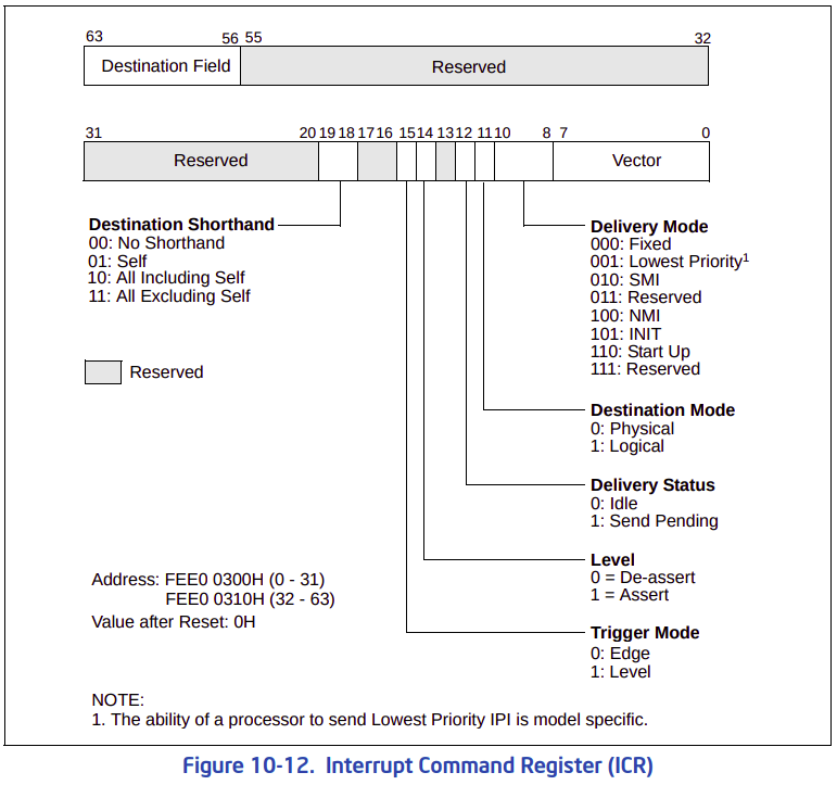
- LINT
: LINT는 `Local Interrupt`의 약자로 Local APIC에 달려있는 2개의 핀을 의미한다. 이 글 맨 앞에서 이미 `LINT` 핀에 대해 언급하긴 했지만, 사실 이 핀은 잘 사용하지 않는 듯 하다. 특별한 기능을 위해서 나왔다기 보다는 호환성을 위해 달려있는 핀인거 같다. 위 `그림 10-8`과 함께 아래의 내용을 참고해서 LINT 관련 레지스터를 어떻게 설정하는지 보자. 이 핀들을 사용하지 않으려면, LINT[0|1] 레지스터에 각각 0x0001_0000을 쓰면 된다.
.....
• LVT LINT0 Register (FEE0 0350H) — Specifies interrupt delivery when an interrupt is signaled at the LINT0 pin.
• LVT LINT1 Register (FEE0 0360H) — Specifies interrupt delivery when an interrupt is signaled at the LINT1 pin.
.....
- 참고 : 10.5.1. Local Vector Table- Local APIC 에러
: 일반적으로 `Intel 64 & IA-32`는 256개의 인터럽트 벡터 번호를 지원한다(`0 ~ 255`). 근데, 여기서 실제로 유효한 인터럽트 벡터는 `16 ~ 255`로 240개의 인터럽트 벡터만 유효하다. 인텔에서는 `0 ~ 31` 까지의 벡터는 CPU가 예약하고 있기 때문에, 사실상 쓰면 안된다. 그런데, LAPIC는 `0 ~ 15` 벡터를 사용하면 오류로 인식하지만, `16 ~ 31`은 오류로 인식하지 않는다고 한다. 그러나, 되도록이면 사용하지 않는게 좋을 것 같다.
The Intel 64 and IA-32 architectures define 256 vector numbers, ranging from 0 through 255 (see Section 6.2, “Exception and Interrupt Vectors”). Local and I/O APICs support 240 of these vectors (in the range of 16 to 255) as valid interrupts.
When an interrupt vector in the range of 0 to 15 is sent or received through the local APIC, the APIC indicates an illegal vector in its Error Status Register (see Section 10.5.3, “Error Handling”). The Intel 64 and IA-32 architectures reserve vectors 16 through 31 for predefined interrupts, exceptions, and Intel-reserved encodings (see Table 6-1). However, the local APIC does not treat vectors in this range as illegal.
When an illegal vector value (0 to 15) is written to an LVT entry and the delivery mode is Fixed (bits 8-11 equal 0), the APIC may signal an illegal vector error, without regard to whether the mask bit is set or whether an interrupt is actually seen on the input.
- 참고 : 10.5.2 Valid Interrupt Vectors: `ESR`은 인터럽트 핸들리 도중에 에러가 발생하면, 여기에 해당 에러에 대한 내용이 작성된다. 이 `Error Status Register`는 재미있는게 `READ/WRITE` 레지스터다.
The local APIC records `errors detected during interrupt handling` in the error status register (ESR). The format of the ESR is given in Figure 10-9; it contains the following flags:
....
The ESR is a `write/read` register. Before attempt to read from the ESR, software should first write to it. (The value written does not affect the values read subsequently; only zero may be written in x2APIC mode.) This write clears any previously logged errors and updates the ESR with any errors detected since the last write to the ESR. This write also rearms the APIC error interrupt triggering mechanism.
The LVT Error Register (see Section 10.5.1) allows specification of the vector of the interrupt to be delivered to the processor core when APIC error is detected. The register also provides a means of masking an APIC-error interrupt. This masking only prevents delivery of APIC-error interrupts; the APIC continues to record errors in the ESR.
....
- 참고 : 10.5.3 Error Handling
• LVT Error Register (FEE0 0370H) — Specifies interrupt delivery when the APIC detects an internal error (see Section 10.5.3, “Error Handling”).
...
- 참고 : 10.5.1 Local Vector Table: 위의 내용을 요약하면 다음과 같다
0" ESR은 읽기/쓰기가 가능한 레지스터다. ESR에 `읽기`를 시도하기전에 반드시 OS는 먼저 여기에 뭔가를 써야한다. 일반적으로, `0`을 쓴다. 이렇게 ESR을 읽기 전에 `0`을 씀으로써 ESR에 들어있던 이전값들이 리셋된다.
1" `LVT Error Register` 는 APIC가 에러를 인지했을 때, 프로세서로 전달할 인터럽트 벡터를 명시하는 레지스터다. 즉, APIC가 에러를 인지하면, `LVT Error Register`에 명시되어 있는 인터럽트 벡터를 프로세서에게 전달한다. 그리고 이 레지스터는 `MASK` 기능 또한 가지고 있다.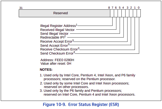
- Local APIC 버전
: 현재 시스템의 APIC의 버전을 확인할 수 가 있다. 그런데, 사실 APIC 버전보다는 프로세서의 버전을 알려준다고 하는게 맞다. 예를 들어, 이 레지스터를 통해서 `펜티엄 4 혹은 제온 시리즈`인지, `펜티임 6 시리즈`인지 등을 알 수 있다. [7:0] 비트는 현대에는 의미가 없다. [7:0]이 `0`이면, APIC가 프로세서 외부에 있고, `10H - 15H`면 프로세서 온 칩이다. 그런데, 현대에는 LAPIC는 프로세서 온 칩으로 되어있다. 결국, `MAX LVT Entry`를 통해 현재 프로세서의 버전을 알아내야 한다.
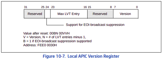
: `MAX LVT Entry`가 5이면 프로세서 모델은 `펜티엄 4 & 제온`인 것이다. 4면 `펜티임 6` 시리즈가 된다.
Shows the number of `LVT entries minus 1`. For the Pentium 4 and Intel Xeon processors (which have `6 LVT entries`), the value returned in the Max LVT field is 5; for the P6 family processors (which have `5 LVT entries`), the value returned is 4; for the Pentium processor (which has 4 LVT entries), the value returned is 3. For processors based on the Intel microarchitecture code name Nehalem (which has 7 LVT entries) and onward, the value returned is 6.
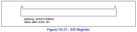
- 참고 : 10.4.8 Local APIC Version Register- Local APIC EOI
: `EOI`의 개념은 PIC때 부터 존재해오던 개념이다. `EOI`는 프로세서가 인터럽트 처리루틴이 끝났을 경우, 인터럽트 컨트롤러에게 전달하는 메세지다. 즉, 다음 인터럽트를 처리할 준비가 되어있다는 의미가 담긴 메시지다. APIC에서 재미있는 건, 레벨 트리거로 설정된 인터럽트에 대한 처리가 마무리가 되서 IO APIC에게 EOI를 전송할 경우, LAPIC는 모든 IO APIC에게 EOI를 브로드 캐스팅한다는 것이다.
For all interrupts except those delivered with the NMI, SMI, INIT, ExtINT, the start-up, or INIT-Deassert delivery mode, the interrupt handler must include a write to the end-of-interrupt (EOI) register (see Figure 10-21). This write must occur at the end of the handler routine, sometime before the IRET instruction. This action indicates that the servicing of the current interrupt is complete and the local APIC can issue the next interrupt from the ISR.
Upon receiving an EOI, the APIC clears the highest priority bit in the ISR and dispatches the next highest priority interrupt to the processor. If the terminated interrupt was a level-triggered interrupt, the local APIC also sends an end-of-interrupt message to all I/O APICs.
System software may prefer to direct EOIs to specific I/O APICs rather than having the local APIC send end-ofinterrupt messages to all I/O APICs.
.....
- 참고 : 10.8.5 Signaling Interrupt Servicing Completion: 근데, 시스템 소프트웨어 같은 로우 레벨 프로그램들은 최적화를 진행해야 할 경우가 많다. 즉, EOI를 브로드 캐스팅하는게 아니라, 특정 IO APIC에게 직접적으로 EOI를 전송하는 경우가 필요할 수 있다. 이럴 때, `Spurious Interrupt Vector Registers`의 12번 비트를 SET하면, EOI를 브로드 캐스팅하지 않는다. 이러한 기능을 `EOI Broadcast Suppression` 이라고 한다.
: 근데 이 기능을 무조건 쓸 수 있는 건 아니다. `Local APIC Version Register`의 24번 비트가 SET이면, `EOI Broadcast Suppression`를 지원한다는 뜻이다.
- Local APIC 인터립트 인지
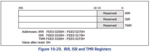
: Local APIC에서는 PIC와 다르게 IMR 레지스터가 사라졌다. 그리고 APIC 부터는 우선순위를 인터럽트 번호로 평가하지 않는다. 아래의 `two interrupt pending registers`는 IRR과 ISR을 의미한다. 그리고, 이 레지스터들은 APIC가 도입되면서 인터럽트 벡터 번호를 `0 ~ 255`까지 할당이 가능하기 때문에 256비트까지 확장시켰다. `0 ~ 15`는 APIC에서 예약한 번호라서 사용이 불가능하다(LAPIC는 `0 ~ 15` 벡터까지만 오류로 인식하지만, 실제로는 `0 ~ 31` 까지 예약되어 있기 때문에 사용하면 안된다). 참고로, 아래에 `fixed interrupt`는 LAPIC에서 `Delivery Mode`를 `Fixed`로 설정했을 때의 인터럽터를 의미한다. `fixed interrupt`는 인터럽트 벡터 번호를 그대로 프로세서에게 전달되는 것을 의미한다.
The local APIC queues the fixed interrupts that it accepts in one of two interrupt pending registers: the interrupt request register (IRR) or in-service register (ISR). These `two 256-bit read-only registers` are shown in Figure 10-20. The 256 bits in these registers represent the 256 possible vectors; vectors 0 through 15 are reserved by the APIC (see also: Section 10.5.2, “Valid Interrupt Vectors”).
The IRR contains the active interrupt requests that have been accepted, but not yet dispatched to the processor for servicing. When the local APIC accepts an interrupt, it sets the bit in the IRR that corresponds the vector of the accepted interrupt. When the processor core is ready to handle the next interrupt, the local APIC clears the highest priority IRR bit that is set and sets the corresponding ISR bit. The vector for the highest priority bit set in the ISR is then dispatched to the processor core for servicing.
While the processor is servicing the highest priority interrupt, the local APIC can send additional fixed interrupts by setting bits in the IRR. When the interrupt service routine issues a write to the EOI register (see Section 10.8.5, “Signaling Interrupt Servicing Completion”), the local APIC responds by clearing the highest priority ISR bit that is set. It then repeats the process of clearing the highest priority bit in the IRR and setting the corresponding bit in the ISR. The processor core then begins executing the service routing for the highest priority bit set in the ISR.
If more than one interrupt is generated with the same vector number, the local APIC can set the bit for the vector both in the IRR and the ISR. This means that for the Pentium 4 and Intel Xeon processors, the IRR and ISR can queue two interrupts for each interrupt vector: one in the IRR and one in the ISR. Any additional interrupts issued for the same interrupt vector are collapsed into the single bit in the IRR.
For the P6 family and Pentium processors, the IRR and ISR registers can queue no more than two interrupts per interrupt vector and will reject other interrupts that are received within the same vector.
If the local APIC receives an interrupt with an interrupt-priority class higher than that of the interrupt currently in service, and interrupts are enabled in the processor core, the local APIC dispatches the higher priority interrupt to the processor immediately (without waiting for a write to the EOI register). The currently executing interrupt handler is then interrupted so the higher-priority interrupt can be handled. When the handling of the higher-priority interrupt has been completed, the servicing of the interrupted interrupt is resumed.
The trigger mode register (TMR) indicates the trigger mode of the interrupt (see Figure 10-20). Upon acceptance of an interrupt into the IRR, the corresponding TMR bit is cleared for edge-triggered interrupts and set for leveltriggered interrupts. If a TMR bit is set when an EOI cycle for its corresponding interrupt vector is generated, an EOI message is sent to all I/O APICs.
.....
- 참고 : 10.8.4 Interrupt Acceptance for Fixed Interrupts: 위의 내용을 요약하면 다음과 같다.
0" Local APIC가 인터럽트를 인지하면, 제일 먼저 해당 인터럽트에 대응하는 IRR의 비트를 SET한다. 프로세서가 인터럽트를 받아들일 준비가 되면, Local APIC는 IRR 레지스터에서 SET 되어있는 비트(인터럽트 벡터)중 가장 우선순위가 높은 비트를 CLEAR 한다. 그러면서, 동시에 대응하는 ISR 비트를 SET 한다. ISR에 대응하는 비트가 SET 되는 순간 해당 비트에 대응하는 인터럽트가 프로세서로 전달되고 프로세서는 처리를 시작한다.
1" 프로세서가 인터럽트를 처리하는 동안에도 Local APIC는 추가적인 인터럽트를 인지할 수 있다. 이 인터럽트들은 IRR 비트에 SET 된다. 인터럽트 서비스 루틴 마지막 시점에 `EOI 레지스터`를 쓰게 되는데, 이 때 그걸 감지한 Local APIC는 ISR 레지스터에서 SET 되어있는 비트중 가장 높은 우선순위 비트를 CLEAR 한다. 그리고 다시 IRR 레지스터에서 가장 우선순위가 높은 비트를 CLEAR 하고, 그에 대응하는 ISR 레지스터를 SET 하는 과정을 반복한다.: IRR 레지스터는 `대기 인터럽트`를 놓아온 레지스터이고, ISR 레지스터는 `현재 실행 중인 인터럽트`를 의미하는 레지스터다. 그런데, 동일한 인터럽트 벡터가 동시에 2번 발생하면 어떻게 될까? 모델에 따라 차이가 있다. 펜티임4 및 제온 시리즈에서는 IRR 뿐만 아니라 ISR까지 해당 인터럽트 벡터에 대응하는 비트를 SET한다. 즉, IRR과 ISR의 특정 비트가 둘다 1이라면, 그 인터럽트 벡터는 2번이상 발생한 인터럽트라고 생각하면 된다. 만약, 3번 발생하면 ? 무시된다(정확히는 IRR에서 `collapse` 한다). 펜티엄 6 시리즈는 2개의 동일 인터럽트 벡터에 대해 한 개만 인식한다.
: 만약, 현재 프로세서가 처리하고 있는 인터럽트보다 `interrupt-priority class`가 높은 인터럽트가 발생하면, 프로세서가 인터럽트 또한 활성화가 되어있는 상태라면(IF 플래그 CLEAR), LAPIC는 EOI를 기다리지도 않고, 즉각적으로 우선선위가 높은 인터럽트를 프로세서에게 전달한다. 여기서 주의점이 있다. 로컬 프로세서의 IF 플래그가 CLEAR가 되어있는 상황이어야 한다. 즉, IF 플래그 CLEAR면 현재 실행중 인 인터럽트가 대기중인 인터럽트보다 우선순위가 낮아도 선점되지 않는다. 즉, IF 플래그가 SET이면, 인터럽트의 선점은 없다. 프로세서는 현재 처리중인 인터럽트를 우선순위에 밀려 선점하고, 더 높은 우선순위의 인터럽트를 처리하게 된다. 더 높은 우선순위의 인터럽트를 처리가 완료되면, 그제서야 이전에 선점되었던 인터럽트 처리를 다시 재개한다.
: 그리고, TMR(Trigger-mode register)는 인터럽트의 트리거 모드를 나타낸다. 외부 인터럽트가 들어오면, 매핑된 인터럽트 벡터가 IRR 레지스터에 SET된다. 이 때, 인터럽트가 엣지 트리거이면 TMR에는 `0`으로, 레벨 트리거면 `1`로 세팅된다. 즉, 인터럽트 벡터 3번이 감지되서 IRR[3]이 SET 되고, 이 인터럽트가 레벨 트리거면 TMR[3]은 1로 SET 된다. 엣지 트리거였다면, TMR[3]은 0이 된다.
: 잊으면 안되는 내용이 있다. 아래에 명시된 인터럽트들은 IRR이나 ISR을 거치지 않고, 곧바로 프로세스에게 전달되어 서비스된다는 것.
All interrupts with an NMI, SMI, INIT, ExtINT, start-up, or INIT-deassert delivery mode bypass the IRR and ISR registers and are sent directly to the processor core for servicing.
- Interrupt Priority
: LAPIC에서 프로세서로 전달되는 모든 인터럽트들은 벡터 번호를 기반으로 우선 순위를 갖는다(여기서 벡터 번호는 당연히 물리적인 하드웨러 라인 번호가 아니다). 여기서 중요한 게, APIC는 기존 PIC와는 다르게 물리적인 하드웨어 번호로 인터럽트 우선순위를 판단하지 않는다. IO APIC는 자신에게 들어오는 외부 인터럽트 하나하나에 대해 `IO 리다이렉션 테이블 엔트리`를 생성할 수 있다. 이 엔트리에는 IO APIC에게 들어온 외부 인터럽트를 어떤 LAPIC에게로 전달할 것인지, 인터럽트 벡터 번호등을 명시할 수 있다. 여기서 인터럽트 벡터 번호는 논리적인 번호다. HW적인 외부 인터럽트 번호를 SW적인 인터럽트 벡터 번호로 매핑하는 것이다.
: LAPIC는 IO APIC에게 받은 인터럽트 벡터의 우선순위를 판단해서 현재 동작중인 프로세서에게 전달받은 인터럽트를 곧 바로 서비스시킬 것인지를 판단한다. 인터럽트 벡터는 8비트를 차지한다. 근데, 여기서 상위 4비트와 하위 4비트가 각각 다른 역할은 한다.

: 상위 4비트를 `인터럽트 우선순의 클래스`라고 한다. 이 클래스에 유효한 값은 `1 ~ 15`가 유효하며, 숫자가 클 수록 우선순위가 증가한다. 즉, 15가 가장 쌘 인터럽트 우선순위 클래스이며, 1이 가장 작은 우선순위다. 그렇면, 인터럽트는 15개가 한계라는 말이냐? 그렇지 않다. 이게 클래스와 벡터를 곱해서 실제 벡터 번호가 생성된다. 예를 들어, 실제 21번 인터럽트 벡터는 인터럽트 우선순위 클래스가 1이고, 인터럽트 벡터는 6 이어야 한다. 실제 47번 인터럽트 우선순위 클래스는 2번, 인터럽트 우선순위 클래스와 인터럽트 벡터는 15여야 한다. CPU가 예약한 인터럽트는? 그래서 실제 유효한 인터럽트 우선순위 클래스는 사실 `2~15` 범위를 갖는다(0 ~ 31은 예약되어 있으므로). 그렇다면, 동일 클래스 내에서는 어떻게 인터럽트 우선순위를 판단하지? 여기서는 인터럽트 벡터가 클수록 우선순위가 높다고 본다.
- Task Priority Register
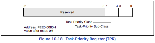
: `TPR`은 우선순위 인터럽트를 설정하는 레지스터가 아니다. `임계값`을 설정하는 레지스터다.
The local APIC also defines a task priority and a processor priority that determine `the order` in which interrupts are handled. The task-priority class is the value of bits 7:4 of the task-priority register (TPR), which can be written by software (TPR is a read/write register); see Figure 10-18.
The task priority allows software to set a `priority threshold for interrupting the processor`. This mechanism enables the operating system to temporarily block low priority interrupts from disturbing high-priority work that the processor is doing. The ability to block such interrupts using task priority results from the way that the TPR controls the value of the processor-priority register (PPR).5
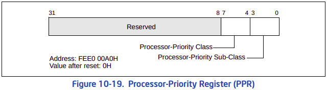
The processor-priority class is a value in the range 0–15 that is maintained in bits 7:4 of the processor-priority register (PPR); see Figure 10-19. The PPR is a `read-only` register. The processor-priority class represents the `current priority` at which the processor is executing.
....
....
The processor-priority class determines the priority threshold for interrupting the processor. The processor will deliver only those interrupts that have an interrupt-priority class higher than the processor-priority class in the PPR. If the processor-priority class is 0, the PPR does not inhibit the delivery any interrupt; if it is 15, the processor inhibits the delivery of all interrupts. (The processor-priority mechanism does not affect the delivery of interrupts with the NMI, SMI, INIT, ExtINT, INIT-deassert, and start-up delivery modes.)
The processor does not use the processor-priority sub-class to determine which interrupts to delivery and which to inhibit. (The processor uses the processor-priority sub-class only to satisfy reads of the PPR.)
- 참고 : 10.8.3.1 Task and Processor Priorities
....
....
System software can use the TPR register to temporarily block low-priority interrupts from interrupting a high-priority task. This is accomplished by loading TPR with a value corresponding to the highest-priority interrupt that is to be blocked. For example, loading TPR with a value of 9 (1001b) blocks all interrupts with a priority class of 9 or less, while allowing all interrupts with a priority class of 10 or more to be recognized. Loading TPR with 0 enables all external interrupts. Loading TPR with 15 (1111b) disables all external interrupts.
....
- 참고 : https://en.wikipedia.org/wiki/Control_register#CR8: 위의 내용을 요약하면 다음과 같다.
0" TPR과 PPR을 통해 인터럽트의 처리 순서를 결정한다. TRP[7:4] 영역은 `Task-Priority Class` 영역은 현재 프로세서가 인터럽트가 걸릴 임계값을 설정한다. 즉, `Task-Priority Class`에 설정된 값보다 낮은 순위의 인터럽트들은 인터럽트로 인식되지 않는다.
1" PPR은 `READ-ONLY` 레지스터이며, 현재 실행 중인 프로세서의 우선순위를 나타낸다. PPR은 TRP과 ISRV를 통해서 계산된다. 프로세서는 PPR의 `processor-priority class` 보다 높은 우선순위를 갖는 `interupt-priority class`를 프로세서에게 전달한다.: TPR에 0을 쓰면, 모든 인터럽트를 허용하고, TPR에 15를 쓰면 모든 인터럽트를 허용하지 않는다는 뜻이다. 만약, 9를 쓰면, 9와 같거나 9보다 작은 인터럽트들은 모두 인지하지 않는다. 그리고, PTR의 `processo-priority sub class`는 신경쓰지 않아도 될 것 같다.
: 그렇다면, `TPR`과 `PPR` 차이가 뭘까? 둘 다 인터럽트를 허용하지 않는 것 같은데, 무슨 차이가 있을까? 결론부터 말하자면, 프로세서는 `PPR`의 `processo-priority class`를 통해서 인터럽트를 프로세서에게 전달할지 말지를 결정한다. 인텔 스펙에서 `PPR[7:4]`를 결정하는 방법은 다음과 같다.
The value of the PPR is based on the value of TPR and the value ISRV; ISRV is the vector number of the highest priority bit that is set in the ISR or 00H if no bit is set in the ISR. (See Section 10.8.4 for more details on the ISR.) The value of PPR is determined as follows:
• PPR[7:4] (the processor-priority class) the maximum of TPR[7:4] (the task- priority class) and ISRV[7:4] (the priority of the highest priority interrupt in service).
- 참고 : 10.8.3.1 Task and Processor Priorities
On x86-64, there is TPR (task-priority register; writeable) and PPR (processor-priority register; read-only; basically the max of TPR and the currently-active interrupt's priority). An interrupt's 8-bit vector number is used as its priority. The top 4 bits are the priority class. The CPU will only handle an interrupt with a priority class higher than PPR. That means an interrupt can only be preempted by one of higher priority than itself, and TPR can be used to mask all interrupts up to a given priority (e.g. a kernel critical section can disable most interrupts, but still allow preemption by the highest-priority ones to meet certain real-time requirements).
- 참고 : https://lwn.net/Articles/918323/: `PPR[7:4]`는 TPR과 ISRV를 통해서 정해진다. ISRV는 ISR에 SET 되어 있는 가장 우선순위가 높은 인터럽트 벡터를 의미한다. 즉, 프로세서에서 현재 실행중인 인터럽트 벡터를 의미한다고 보면 된다. `PPR[7:4]`는 TPR과 ISRV의 MAX값으로 정해진다. 예를 들어, TPR[7:4]를 2라고 세팅했다고 하자. 그리고, 현재 처리가 중인 인터럽트가 없다면, ISR이 0이 되니, ISRV도 0이 된다. 그렇면, PPR은 2가 된다. 또 다른 예시로, IO APIC로 부터 인터럽트 벡터가 14이고, 인터럽트 우선순위가 4인 인터럽트를 받았다. 현재 실행중인 인터럽트는 우선순위가 4이고, 인터럽트 벡터가 2라고 치자. 그렇면, PPR은 4가 세팅된다. 결국, IO APIC에게 받은 인터럽트는 우선순위에게 밀려 LAPIC는 프로세서에게 전달하지 않는다.
'프로젝트 > 운영체제 만들기' 카테고리의 다른 글
CMOS (0) 2023.07.22 [xv6] Local APIC (0) 2023.07.21 [멀티프로세서] Multi-Processor Specification(MPS) (0) 2023.07.18 [xv6] Scheduling (0) 2023.07.17 [xv6] Spinlock (0) 2023.07.17