" 이 글을 시작하기 전에 먼저 당부해야 할 부분이 있다. boot ROM code 는 대개 RAM 에 mapped 된다고 생각하는데, 우리가 아는 RAM 은 on-chip 이 아니다(SoC 를 조금만 공부하면 알 수 있는 내용이다). DRAM 사이즈가 크기 때문에, 항상 externel device 로 취급된다. 그렇다면, boot ROM 이 특정 address space 로 mapped 된다는 내용을 자주 보게 되는데, 이건 무슨 소리일까? DRAM 에 mapped 되는게 아니었나? boot ROM 이 mapped 되는 곳은 CPU address pin 에 mapped 된다고 보는 것이 맞다. 예를 들어, Intel Arria 10 SoC 의 boot ROM code 는 128KB 를 차지하며, on-chip ROM 에 저장되어 있다. 그리고, on-chip ROM 은 addresses 0xFFFC_0000 ~ 0xFFFD_FFFF 에 mapped 된다. 여기서
" 그리고, memory map 과 memory mapped I/O 는 엄연히 다르다. memory mapped I/O 는 CPU 와 I/O devices 들이 데이터 통신을 위해 사용하는 mechanism 을 의미하고, memory map 은 말 그대로 RAM 을 어떻게 layout 했는지를 의미한다.
- Operation
" 전원 공급되고 CPU가 최초에 시작되는 시점에는 모든 하드웨어들이 초기화가 되어있지 않다. 이 때, RAM도 초기화되어 있지 않다. 당연히, 디스크 드라이브 컨트롤러도 초기화되어 있지 않아서, 실행할 코드를 디스크 드라이브에서 가져올 수 도 없다. 이 때, 비휘발성이면서 RAM 처럼 접근이 가능한 메모리가 있다. 바로 `ROM` 이다. CPU가 실행해야 할 코드가 `ROM`에 이미 저장되어 있다.
: 우리가 흔히, 코드를 실행하기 위해 디스크에서 프로그램을 가져와서 RAM에 로드한다고 한다. ROM 에서도 마찬가지다. ROM에 있는 코드는 이미 로드가 된 코드라서 CPU 에서 바로 실행이 가능하다. 그런데, 디스크와 RAM이 차이가 있을까? 즉, 디스크에서는 코드를 실행하지 못하는 것일까? 사실 RAM이건 디스크건 모든 스토리지 디바이스에서는 코드를 실행할 수 없다. 명령어를 실행하는 것은 CPU다. 즉, 명령어를 CPU 내부로 가져와서 CPU안에 연산 유닛들이 실행하는 것이다. 단지, `디스크안에 프로그램을 RAM에 로드하고 CPU가 실행한다` 말의 의미는 CPU가 디스크와 통신하면서 데이터를 처리하는 속도보다 RAM과 통신하면서 데이터를 처리하는 속도가 빠르기 때문에 위와 같은 말이 생긴 것이다.
Upon power up, hardware usually starts uninitialized. To continue booting, the system may need to read a bootloader from some peripheral device. It is often easier to implement routines for reading from external storage devices in software than in hardware. A boot ROM provides a place to store this `initial loading code`, at a `fixed location``immediately available` to the processor when execution starts.
The boot ROM is mapped into memory at a fixed location, and the processor is designed to start executing from this location after reset. Usually, it is placed on the same die as the CPU, but it can also be an external ROM chip, as is common in older systems.
The boot ROM will then initialize the hardware busses and peripherals needed to boot. In some cases the boot ROM is capable of initializing RAM, and in other cases it is up to the bootloader to do that.
At the end of the hardware initialization, the boot ROM will try to load a bootloader from external peripheral(s) (like an eMMC, a microSD card, an external EEPROM, and so on) or through specific protocol(s) on a bus for data transmission (like USB, UART, etc). ...
- 참고 : https://en.wikipedia.org/wiki/Boot_ROM
- Suspend-to-RAM
When a system on a chip enters suspend to RAM mode, in many cases, the processor is completely off while the RAM is put in self refresh mode. At resume, the boot ROM is executed again and many boot ROMs are able to detect that the system on a chip was in suspend to RAM and can resume by jumping directly to the kernel which then takes care of powering on again the peripherals which were off and restoring the state that the computer was in before.
- 참고 : https://en.wikipedia.org/wiki/Boot_ROM
- Arria 10 SoC Boot Code
"
- TI DSP Boot ROM
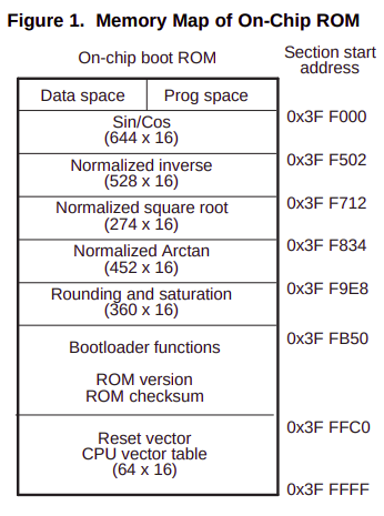
" Boot ROM 코드는 공장에서 생상되는 시점에 CPU 의 특정 physical address space 로 mapping 된다. 예를 들어, TMS320x280x, 2801x, 2804x 칩들은 0x3F_F000 - 0x3F_FFFF 로 mapping 된다. 사이즈는 4KB 로 차지한다. 이 4KB 는 다시 16B 로 나누어 총 256 개의 blocks 들로 나누어져 있다.
TMS320x280x, 2801x, 2804x DSP Boot ROM Reference Guide (Rev. C)
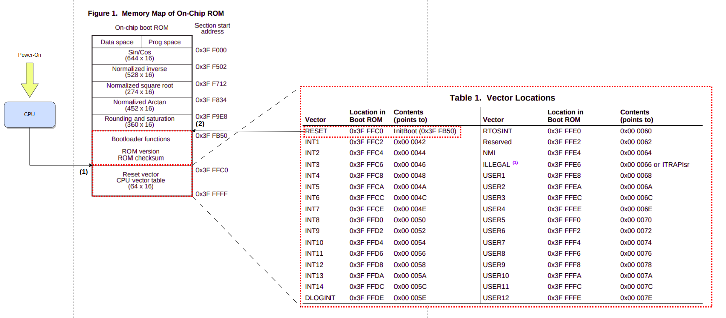
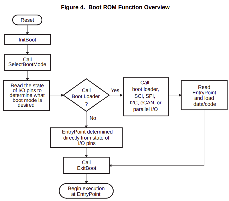
" internal boot ROM memory 에서 핸들링되는 유일한 vector 는 0x3F_FFC0 에 저장되어 있는 `reset vector` 다. 즉, boot ROM 에게 할당받은 0x3F_F000 - 0x3F_FFFF 내에서 유일하게 처리가 가능한 vector 가 reset vector 라는 뜻이다. 왜, 그럴까? 이건 reset vector 가 공장에서 양산될 때, boot ROM 에 저장되어 있는 `initBoot function` 을 가리키도록 설계되어 있기 때문이다. 즉, TMS320x280x, 2801x, 2804x 칩들은 전원을 인가하면 하드웨어적으로 initBoot 함수를 호출한다는 것이다. 여기서 기본적인 devie initialization 을 수행한 후, GPIO pins 검사해서 어떤 boot mode 를 사용할지를 결정하게 된다.
TMS320x280x, 2801x, 2804x DSP Boot ROM Reference Guide (Rev. C)
" TMS320x280x, 2801x, 2804x 의 Boot ROM code 에서 어떤 작업들을 수행하는지 알아보자.
1. external source(NAND, eMMC, SD card 등) 에 있는 secondary boot loader code 를 internal memory 에 transfer 한다. 이렇게 하는 이유는 externally non-volatile 처럼 느린 메모리에서 code 를 실행하는 것보다는 internal memory(cache) 처럼 high-speed memory 에서 실행하는 것이 더 빠르기 때문이다.
2. Boot ROM code 는 다양한 storage memory(NAND, eMMC, SD card 등) 로 부터 secondary boot loader 를 load 할 수 있도록 제작되어 있다. 이 때, GPIO 를 통해서 어떤 storage memory 에서 secondary boot loader 를 load 해야 할 지를 결정한다.
TMS320x280x, 2801x, 2804x DSP Boot ROM Reference Guide (Rev. C)
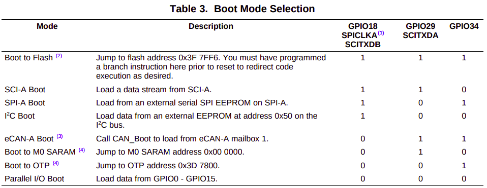
" boot ROM code 는 3개의 GPIO 를 검사해서 어떤 boot mode 를 사용하는지 검사한다. 아래에서 볼 수 있다시피, TMS320x280x, 2801x, 2804x 칩은 총 8개의 boot mode 를 지원한다.
TMS320x280x, 2801x, 2804x DSP Boot ROM Reference Guide (Rev. C)
"
TMS320x280x, 2801x, 2804x DSP Boot ROM Reference Guide (Rev. C)
" TMS320C28x CPU instruction 명령어는이 문서를 참고하자. LCR 은 _SelectBootMode 함수를 호출하는 명령어다. 그리고, _SelectBootMode 가 호출된 후, ACC 레지스터(TI 가 정의한 레지스터)에 EntryAddr 이 저장된다.
;-----------------------------------------------
; _InitBoot
;-----------------------------------------------
;-----------------------------------------------
; This function performs the initial boot routine
; for the boot ROM.
;
; This module performs the following actions:
;
; 1) Initalizes the stack pointer
; 2) Sets the device for C28x operating mode
; 3) Calls the main boot functions
; 4) Calls an exit routine
;- ----------------------------------------------
_InitBoot:

; Initalize the stack pointer.

__stack: .usect ".stack",0
	MOV SP, #__stack ; Initalize the stack pointer

; Initalize the device for running in C28x mode.

	C28OBJ ; Select C28x object mode
	C28ADDR ; Select C27x/C28x addressing
	C28MAP ; Set blocks M0/M1 for C28x mode
	CLRC PAGE0 ; Always use stack addressing mode
	MOVW DP,#0 ; Initialize DP to point to the low 64 K
	CLRC OVM

; Set PM shift of 0
	SPM 0

; Decide which boot mode to use
	LCR _SelectBootMode

; Cleanup and exit. At this point the EntryAddr
; is located in the ACC
	BF _ExitBoot,UNC
" 아래 보면, `.sect ".BootVecs"` 를 통해서 Boot ROM vector table 을 생성하고 있다. 그런데, .BootVecs 섹션이 물리적으로 0x3F_FFC0 에 위치한다는 것은 어떻게 알 수 있을까? 이건 링크스크립트를 확인해봐야 한다. 아마, TMS320x280x, 2801x, 2804x 칩을 컴파일할 때, 사용하는 링크스크립트에 .BootVecs 섹션은 0x3F_FFC0 에 위치하도록 할 것이다.
;eof ----------
;; TI File $Revision: /main/3 $
;; Checkin $Date: May 2, 2006 20:49:30 $
;;###########################################################################
;;
;; FILE: Vectors_Boot.h
;;
;; TITLE: Boot Rom vector table.
;;
;; Functions:
;;
;; This section of code populates the vector table in the boot ROM. The reset
;; vector at 0x3FFFC0 points to the entry into the boot loader functions (InitBoot())
;; The rest of the vectors are populated for test purposes only.
;;
;;###########################################################################
;; $TI Release:$
;; $Release Date:$
;;###########################################################################
;-----------------------------------------------------------
; The vector table located in boot ROM at 0x3F FFC0 - 0x3F FFFF
; will be filled with the following data.
;
; Only the reset vector, which points to the InitBoot
; routine will be used during normal operation. The remaining
; vectors are set for internal testing purposes and will not be
; fetched from this location during normal operation.
;
; On the 280x reset is always fetched from this table.
;
;----------------------------------------------------------
.ref _InitBoot
.ref _ITRAPIsr
.sect ".BootVecs"
.long _InitBoot ;Reset
.long 0x000042
.long 0x000044
.long 0x000046
.long 0x000048
.long 0x00004a
.long 0x00004c
.long 0x00004e
.long 0x000050
.long 0x000052
.long 0x000054
.long 0x000056
.long 0x000058
.long 0x00005a
.long 0x00005c
.long 0x00005e
.long 0x000060
.long 0x000062
.long 0x000064
.long _ITRAPIsr ;ITRAP
.long 0x000068
.long 0x00006a
.long 0x00006c
.long 0x00006e
.long 0x000070
.long 0x000072
.long 0x000074
.long 0x000076
.long 0x000078
.long 0x00007a
.long 0x00007c
.long 0x00007e
" 아래 코드에서 `.BootVecs : load = VECS` 를 볼 수 있다. VECS 는 뭘까? 위에 올라가면 `VECS : origin = 0x3FFFC0` 인것을 알 수 있다. 즉, `.BootVecs : load = 0x3FFFC0` 임을 알 수 있다. 결국, .BootVecs 가 0x3FFFC0 에 load 됨을 의미한다.