-
[리눅스 커널] PM - Regulator framework : overview & devicetreeLinux/kernel 2023. 8. 7. 19:24
글의 참고
- https://www.kernel.org/doc/html/next/power/regulator/overview.html
- https://elinux.org/images/c/c1/Regulator-api-celf.pdf
- http://www.wowotech.net/pm_subsystem/regulator_framework_overview.html
- Linux Device Driver Development - By John Madieu
- https://www.kernel.org/doc/html/v4.12/driver-api/regulator.html
- https://www.kernel.org/doc/Documentation/devicetree/bindings/regulator/regulator.yaml
- https://docs.kernel.org/power/regulator/machine.html
- https://android.googlesource.com/kernel/tegra.git/+/2ce2576c4a8fb4942cc3c75d4f81a32138a98f0e/Documentation/devicetree/bindings/regulator/regulator.txt
- https://labcsmart.com/controlling-power-with-the-linux-kernel-regulator-framework/
글의 전제
- 내가 글을 쓰다가 궁금한 점은 파란색 볼드체로 표현했다. 나도 모르기 때문에 나중에 알아봐야 할 내용이라는 뜻이다.
- 밑줄로 작성된 글은 좀 더 긴 설명이 필요해서 친 것이다. 그러므로, 밑 줄 처친 글이 이해가 안간다면 링크를 따라서 관련 내용을 공부하자.
글의 내용
- Overview
" `레귤레이터`란 `Voltage Regulator` 혹은 `Current Regulator`를 일컫는 말로 일정한 전압 및 전류를 유지할 수 있는 장치를 의미한다. 레귤레이터는 전원 리플과 노이즈를 필터링하고 부하에 따라 출력 전압이 변하는 현상을 피하고자 개발한 IC 다.
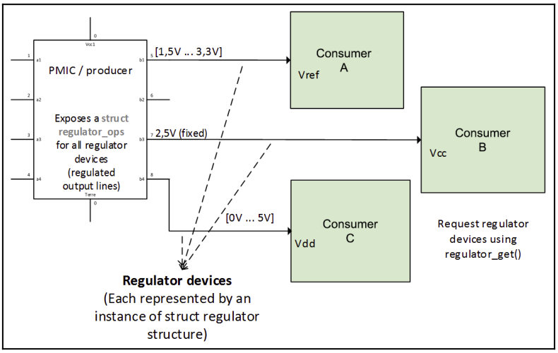
Linux Device Driver Development - By John Madieu- Regulator device-tree [ 참고1 참고2 ]
: 이 글에서는 `Regulator framework` 관련에서 총 3개의 디바이스 트리 문서를 다룬다.
1. regulator.txt : 일반적인 레귤레이터 가이드 문서
2. fixed-regulator.txt : 고정된 output을 제공해야 할 경우
3. gpio-regulator.txt : `gpio`를 레귤레이터용으로 쓸 경우: `fixed-regulator.txt` / `gpio-regulator.txt`는 모두 `regulator.txt`에 작성된 문법을 기반으로, 추가 속성들을 정의하고 있다. 뒤에서 다루겠지만, `fixed-regulator` / `gpio-regulator`는 이미 커널에서 드라이버를 제공하고 있다. 즉, 드라이버 개발자가 즉접 디바이스 트리에서 하드웨어 설정 정보를 가져와서 초기화 및 설정 작업을 해줄 필요가 없다. 단지 `regualtor_get` 함수를 통해 원하는 레귤레이터를 바로 얻을 수 있다. 왜냐면, 부팅 시점에 `fixed-regulator` / `gpio-regulator` 드라이버의 `probe`가 호출되면서 알아서 초기화 작업을 진행해주기 때문이다. 해당 부분은 뒤에서 다시 다룬다.
: 아래 코드는 TI사의 `tps65023` 모델의 디바이스트리다. 인터페이스로 i2c를 사용하고, 주소는 0x48인 것을 알 수 있다. 그리고, 5개의 레귤레이터를 제공하는 것을 확인할 수 있다. 아래 디바이스 트리는 PMIC 드라이버를 개발할 때 자주 사용되는 패턴이다. 참고로, `regulators` 노드는 레귤레이터 프레임워크에서(`regulator.txt`)에서 공식적으로 제공되는 노드가 아니다. 암묵적으로, 여러 제조사에서 `regulators` 노드안에 다수의 레귤레이터들을 작성하고 있다. 물론, `regualtors 노드가 공식적으로 지원하는 노드가 아니기 때문에, 다른 루트 노드를 사용하는 경우도 많다. 대표적으로 퀄컴이 그렇다(퀄컴은 `compatible`에 의존하고 있다. 즉, `compatible`이 `qcom,pm9350-rpmh-regulators` 인 노드안에 레귤레이터 노드들을 작성해야 한다). 그외에 `regulator-*` 속성들은 모두 리눅스 커널 레귤레이터 프레임워크에서 지원해주는 속성들이다.
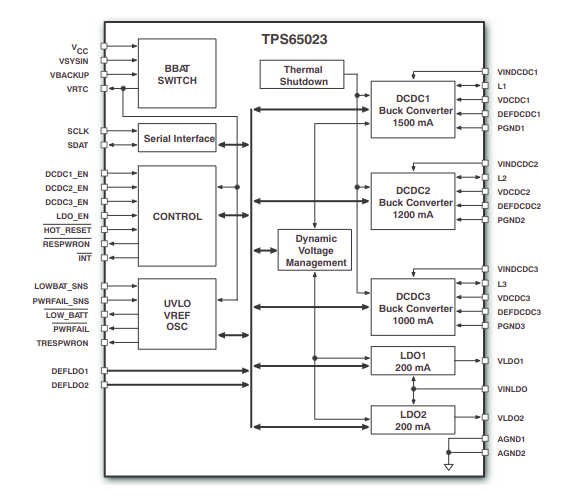
https://elixir.bootlin.com/linux/v6.5/source/Documentation/devicetree/bindings/regulator/tps65023.txt
tps65023@48 {
		compatible = "ti,tps65023";
		reg = <0x48>;

		regulators {
			VDCDC1 {
				regulator-name = "vdd_mpu";
				regulator-always-on;
				regulator-min-microvolt = <1200000>;
				regulator-max-microvolt = <1200000>;
			};

			VDCDC2 {
				regulator-name = "vdd_core";
				regulator-always-on;
				regulator-min-microvolt = <3300000>;
				regulator-max-microvolt = <3300000>;
			};

			VDCDC3 {
				regulator-name = "vdd_io";
				regulator-always-on;
				regulator-min-microvolt = <1800000>;
				regulator-max-microvolt = <1800000>;
			};

			LDO1 {
				regulator-name = "vdd_usb18";
				regulator-always-on;
				regulator-min-microvolt = <1800000>;
				regulator-max-microvolt = <1800000>;
			};

			LDO2 {
				regulator-name = "vdd_usb33";
				regulator-always-on;
				regulator-min-microvolt = <3300000>;
				regulator-max-microvolt = <3300000>;
			};
		};
	};
: 아래 그림은 `TPS65023` 블락다이어 그램이다. 총 5개의 레귤레이터를 확인할 수 있다. 그런데, 위에 작성한 디바이스 트리는 `공급자` 측면에서 작성된 내용이다. 즉, PMIC 드라이버를 만들어야 하는 사람이 작성하는 부분이다. 위에 레귤레이터를 다른 노드에서 가져다 쓰려면 어떻게 작성해야 할까?
https://pdf1.alldatasheet.com/datasheet-pdf/view/154951/TI/TPS65023.html: `<name>-supply = ${공급자 레귤레이터 노드}` 형식으로 공급자가 제공하는 레귤레이터를 사용할 수 있다. 주의할 점은 반드시 접두사가 `-supply` 형태를 지켜줘야 한다. 아래 예제는 `mmc`가 `twl_reg` / `twl_reg2` 레귤레이터를 참조하고 있는 것을 확인할 수 있다.
https://android.googlesource.com/kernel/tegra.git/+/2ce2576c4a8fb4942cc3c75d4f81a32138a98f0e/Documentation/devicetree/bindings/regulator/regulator.txt
    	twl_reg1: regulator@0 {
		...
		...
		...
	};
	twl_reg2: regulator@1 {
		...
		...
		...
	};
	mmc: mmc@0x0 {
		...
		...
		vmmc-supply = <&twl_reg1>;
		vmmcaux-supply = <&twl_reg2>;
	};
: 소스 레벨에서 `twl_reg1` / `twl_reg2` 레귤레이터를 가져오려면, `regulator_get_*` 계열 함수를 사용하면 된다. 두 번째 인자에 접미사 `-supply`를 제거한 이름만 넣어서 공급자가 제공해주는 레귤레이터를 가져올 수 있다.
struct regulator *vmmc = regulator_get(rdev, "vmmc");
struct regulator *vmmcaux = regulator_get(rdev, "vmmcaux");
: 지금까지 알아본 레귤레이터는 가장 일반적인 레귤레이터다. PMIC 드라이버 개발자들은 `regulator.yaml` 문서를 참고해서 직접 디바이스 트리와 드라이버 소스 코드를 작성해야 한다. 그러나, 이번에 설명할 `fixed-regulator`와 뒤에서 설명할 `gpio-regulator`는 개발 방식이 조금 다르다. 대개 이 친구들을 사용하는 경우는 PMIC 드라이버 개발보다는 일반 디바이스 드라이버를 개발하는데, 입력 전원을 GPIO를 통해서 공급받는 경우에 fixed-regulator` / `gpio-regulator`를 사용하게 된다. 이번에는 `fixed-regulator` 에 대해 알아보자. 이 드라이버를 사용하는 목적은 명확하다.
However a fixed voltage regulator is expected to have the regulator-min-microvolt and regulator-max-microvolt to be the same.
- 참고 : https://elixir.bootlin.com/linux/v6.5/source/Documentation/devicetree/bindings/regulator/fixed-regulator.yaml: 즉, 고정적인 전압을 출력해야 하는 경우에 이 레귤레이터를 사용하면 된다. `fixed-regulator`는 고정된 `compatible` 속성을 사용해야 한다. 아래 내용은 `rk3229` 에서 일부분만 빼온 것이다. 아래 노드들이 `regulator-fixed`를 사용하는 것을 볼 수 있다. `fixed-regulator` 드라이버는 `/drivers/regulator/fixed.c` 파일에 구현되어 있다.
//drivers/regulator/fixed.c - v6.5
static const struct of_device_id fixed_of_match[] = {
	{
		.compatible = "regulator-fixed",
		.data = &fixed_voltage_data,
	},
	{
		.compatible = "regulator-fixed-clock",
		.data = &fixed_clkenable_data,
	},
	{
		.compatible = "regulator-fixed-domain",
		.data = &fixed_domain_data,
	},
	{
	},
};
: `fixed-regulator`가 제공하는 자주 사용되는 속성들은 다음과 같다[ 참고1 ].
- Required
1. `compatible`로 반드시 `regulator-fixed`를 사용해야 한다.
2. `regulator-name` 속성을 반드시 명시해야 한다.
- Optional
1. gpio : 사용할 gpio를 명시한다.
2. enable-active-high : `active-high`를 사용할지를 나타낸다. 즉, 해당 레귤레이터에 `1(logic signal)`을 주었을 때, 레귤레이터가 동작하게 할 것이냐를 나타낸다. 만약, 명시하지 않으면 기본 동작은 `active-low`가 된다.
3. vin-supply : 해당 레귤레이터에 전원을 공급해주는 phandle: `fixed voltage regulator`의 가장 중요한 특징은 `regulator-min-microvolt`와 `regulator-max-microvolt`가 같다는 것이다.
// https://elixir.bootlin.com/linux/v5.4.192/source/arch/arm/boot/dts/rk3229-evb.dts
....
    	dc_12v: dc-12v-regulator {
		compatible = "regulator-fixed";
		regulator-name = "dc_12v";
		regulator-always-on;
		regulator-boot-on;
		regulator-min-microvolt = <12000000>;
		regulator-max-microvolt = <12000000>;
	};

	ext_gmac: ext_gmac {
		compatible = "fixed-clock";
		clock-frequency = <125000000>;
		clock-output-names = "ext_gmac";
		#clock-cells = <0>;
	};

	vcc_host: vcc-host-regulator {
		compatible = "regulator-fixed";
		enable-active-high;
		gpio = <&gpio3 RK_PC4 GPIO_ACTIVE_HIGH>;
		pinctrl-names = "default";
		pinctrl-0 = <&host_vbus_drv>;
		regulator-name = "vcc_host";
		regulator-always-on;
		regulator-boot-on;
		vin-supply = <&vcc_sys>;
	};
....
: 이제 마지막으로, `gpio-regulator`에 대해 알아보자. 그런데, `gpio-regulator`는 왜 사용할까? 예를 들어, `fixed-regulator`도 GPIO를 이용하는 것 같은데, 굳이 `gpio-regulator`가 필요할까? `gpio-regulator`는 `fixed-regulator`와는 다르게 동적으로 전압값을 변경할 수 있다는 장점이 있다[참고1 참고2]. 그런데, `gpio-regulator`는 어떻게 전압을 변경시킬까? 사실 GPIO는 `0`과 `1`만 존재하는 라인이다. 즉, 전압도 `voltage level`과 `ground`밖에 없다. `gpio-regulator`에서 논하는 gpio는 일반적인 gpio가 아니다.
GPIO Regulators: GPIOs can also be modelled as regulators where in the high value corresponds to a discrete value of voltage and the low corresponds to another discrete value.
- 참고 : https://elinux.org/images/2/26/PMIC_ELCE_2019.pdf: 즉, gpio가 high value(logical `1`)에서는 3.3V, low value(logical `0`)에서는 1.8V와 같이 동작하도록 설계된 GPIO를 사용해야 한다.
// https://github.com/Xilinx/linux-xlnx/blob/master/arch/arm/boot/dts/r8a7794-alt.dts
    vccq_sdhi0: regulator-vccq-sdhi0 {
		compatible = "regulator-gpio";

		regulator-name = "SDHI0 VccQ";
		regulator-min-microvolt = <1800000>;
		regulator-max-microvolt = <3300000>;

		gpios = <&gpio2 29 GPIO_ACTIVE_HIGH>;
		gpios-states = <1>;
		states = <3300000 1>, <1800000 0>;
	};

	....

	vccq_sdhi1: regulator-vccq-sdhi1 {
		compatible = "regulator-gpio";

		regulator-name = "SDHI1 VccQ";
		regulator-min-microvolt = <1800000>;
		regulator-max-microvolt = <3300000>;

		gpios = <&gpio4 29 GPIO_ACTIVE_HIGH>;
		gpios-states = <1>;
		states = <3300000 1>, <1800000 0>;
	};

    ....

&sdhi0 {
	....
	vmmc-supply = <&vcc_sdhi0>;
	vqmmc-supply = <&vccq_sdhi0>;
	....
};

&sdhi1 {
	....
	vmmc-supply = <&vcc_sdhi1>;
	vqmmc-supply = <&vccq_sdhi1>;
    	....
};
: `gpio-regulator`에서 제공하는 자주 사용되는 속성들은 다음과 같다[참고1 참고2].
- Required
1. compatible : 반드시 `regulator-gpio`를 사용해야 한다.
2. regulator-name : `regulator.txt`에서는 옵션이었지만, `gpio-regulator.txt`에서는 반드시 명시해야 하는 속성이다.
3. gpios : 전압을 조정할 gpio 정보를 입력한다. `gpio2 port`에 29번 핀과 `gpio4 port`에 29번 핀을 의미한다.
4. states : `gpios` 속성에서 작성한 gpio가 어떤 전압값에 매핑되는지를 작성한다. 예시에서는
- Optional
5. enable-gpios : 레귤레이터의 enable/disable 용도로 사용될 gpio를 명시한다.: 그런데, 어떻게 디자인을 해야 GPIO가 `0`에서 1.8V, `1`에서 3.3V가 될 수 있을까? 이건 GPIO 변경했다기 보다는, GPIO 시그널을 받는 곳에서 전압값을 조정하는 구조를 갖고있다. 아래 구조를 보면, PMIC(`DA9063`)에서 `GP2_12` 시그널을 받아서 전압값이 바뀌는 것을 확인할 수 있다.
1. GP2_12 == `1`, VCCQ_SD0 = 3.3V
2. GP2_12 == `0`, VCCQ_SD0 = 1.8V: 즉, 아래와 같은 구조에서 `gpio-regulator`를 이용하는 것이다.
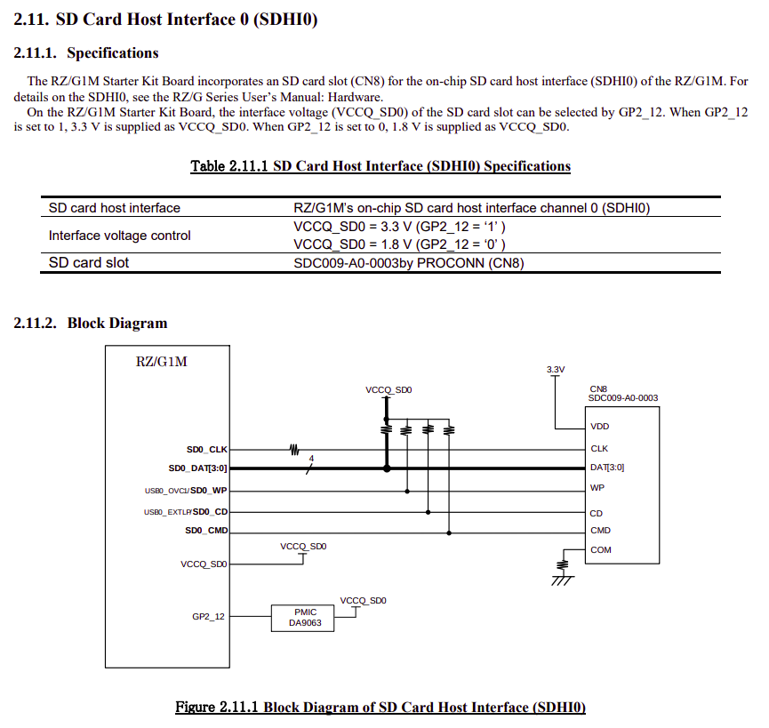
https://elinux.org/images/e/ee/RZG1M_Starter_Kit_BoardHardwareManual.pdf- Regulator sysfs [ 참고1 ]
: `regulator framework`를 통해 커널에 등록된 모든 레귤레이터는 `/sys/class/regulator/` 폴더에 export 된다. 레귤레이터의 `output`이 On 혹은 Off 인지 여부를 알려주는 `state` 속성, 레귤레이터가 `votlage` 레귤레이터인지 `current` 레귤레이터인지 알려주는 `type` 속성등이 있다. 자세한 내용은 `참고1`을 확인하자.
- Case study
: 먼저 `Regulator driver` 를 작성하는 방법에 대해 알아보자. 일반적으로 3가지 함수에 중점을 둔다.
1. Preliminary : PMIC가 지원하는 모든 레귤레이터들에 대한 `struct regulator_desc`를 정의해야 한다. 동적 할당 보다는 전역 변수로 할당한다. 즉, 하드코딩한다. 그리고, 각 레귤레이터에 연결시 킬 `struct regulator_ops`를 정의한다.
1. Probe : `struct regulator_init_data`를 얻어와야 한다. 얻어오는 방법은 2가지가 있다. 첫 번째로 `platform data`에서 얻어올 수 있다. 즉, 옛날에 보드 파일에 하드웨어 사양을 코드로 작성했던 것처럼 하드 코딩하는 것이다. 그리고 반드시 유요한 `struct regulation_constraints` 을 포함하고 있어야 한다. 혹은, 디바이스 트리를 파싱해서 `struct regulation_constraints` 를 만든다. 그리고, `struct regulator_init_data` 를 새롭게 정의한다.
그리고 `struct regulator_config`를 생성하기 위해 이전에 만들어 놓은 `struct regulator_init_data`를 사용한다. 그리고 `regulator_register` 함수에 `struct regulator_desc`와 `struct regulator_config` 를 전달해서 레귤레이터 코어에 새로운 레귤레이터를 등록한다.
등록이 완료되면, `regulator_register` 함수는 `struct regulator_dev` 구조체를 반환한다. 이 구조체는 물리적인 레귤레이터와 1:1 대응하기 때문에, 공급자가 제공하는 API를 사용해서 해당 레귤레이터를 컨트롤 할 수 있다. 컨슈머는 반환받은 `struct regulator_dev`를 별도로 저장해야 놔야한다. 그래야,
2. Remove : 레귤레이터 드라이버가 더 이상 필요없게 되어 메모리에서 제거가 필요할 때, 호출되는 함수다. 동적 할당 받은 모든 리소스들은 모두 여기서 `free`된다. 그리고, `regulator_unregister` 함수를 통해서 등록된 레귤레이터를 제거한다.: `ISL6271A` PMIC를 통해서 간단하게 레귤레이터 프레임워크를 어떻게 사용해야 하는지 알아보자. `ISL6271A`는 기본적으로 `I2C`기반의 PMIC다. 그리고, 3개의 레귤레이터를 가지고 있다.

https://www.renesas.com/us/en/document/dst/isl6271a-datasheet: `ISL6271A` 데이터 시트를 확인해보면, VOUT은 `0.85mV ~ 1.60V` 까지 50mV 단계로 증가하는 `Buck regulator` 인 것을 확인할 수 있다. 그리고, VSRAM & VPLL은 각각 1.1V와 1.3V 고정 전압을 갖는 `Linear regulator`다.


https://www.renesas.com/us/en/document/dst/isl6271a-datasheet: 위의 내용을 토대로 디바이스 트리를 작성하면 아래와 같다.
isl6271a@3c {
  compatible = "isl6271a";
  reg = <0x3c>;
  interrupts = <0 86 0x4>;

  /* supposing our regulator is powered by another regulator */
  in-v1-supply = <&some_reg>;
  [...]

  regulators {
    reg1: core_buck {
      regulator-name = "Core Buck";
      regulator-min-microvolt = <850000>;
      regulator-max-microvolt = <1600000>;
    };

    reg2: ldo1 {
      regulator-name = "LDO1";
      regulator-min-microvolt = <1100000>;
      regulator-max-microvolt = <1100000>;
      regulator-always-on;
    };

    reg3: ldo2 {
      regulator-name = "LDO2";
      regulator-min-microvolt = <1300000>;
      regulator-max-microvolt = <1300000>;
      regulator-always-on;
    };
  };
};
: 이제 드라이버를 작성해보자. 공급자 입장에서 레귤레이터 드라이버를 작성할 때, 제일 먼저 작성할 내용은 `struct regulator_desc` 구조체를 만드는 것이다. 그런데, `struct regulator_desc` 구조체를 만들기 위해서는 반드시 먼저 `struct regulator_ops` 구조체를 정의해야 한다. 기본적으로 레귤레이터의 전압을 변경하는 `.get_voltage_sel` / `.set_voltage_sel` 콜백 함수는 작성한다. 고정 전압 레귤레이터는 전압이 변경되지 않으므로, `.ops`에 `get` / `set` 함수를 작성할 필요가 없다.
//drivers/regulator/isl6271a-regulator.c - v6.5
....
static int isl6271a_get_voltage_sel(struct regulator_dev *dev)
{
	struct isl_pmic *pmic = rdev_get_drvdata(dev);
	int idx;

	....
	idx = i2c_smbus_read_byte(pmic->client);
	....

    return idx;
}

static int isl6271a_set_voltage_sel(struct regulator_dev *dev,
				    unsigned selector)
{
	struct isl_pmic *pmic = rdev_get_drvdata(dev);
	int err;

	....

	err = i2c_smbus_write_byte(pmic->client, selector);
	....

	return err;
}

static const struct regulator_ops isl_core_ops = {
	.get_voltage_sel = isl6271a_get_voltage_sel,
	.set_voltage_sel = isl6271a_set_voltage_sel,
	.list_voltage	= regulator_list_voltage_linear,
	.map_voltage	= regulator_map_voltage_linear,
};

static const struct regulator_ops isl_fixed_ops = {
	.list_voltage	= regulator_list_voltage_linear,
};
: 이제 `struct regulator_desc` 구조체 배열을 만든다. 아래 코드를 보면, 위에서 만든 `struct regulator_ops` 구조체가 `.ops` 필드에 저장되는 것을 확인할 수 있다. 그리고, `LDO1` / `LDO2`는 고정 전압을 사용하기 때문에, `n_voltages` 필드가 1인것을 확인할 수 있다.
//drivers/regulator/isl6271a-regulator.c - v6.5
static const struct regulator_desc isl_rd[] = {
	{
		.name		= "Core Buck",
		.id		= 0,
		.n_voltages	= 16,
		.ops		= &isl_core_ops,
		.type		= REGULATOR_VOLTAGE,
		.owner		= THIS_MODULE,
		.min_uV		= ISL6271A_VOLTAGE_MIN,
		.uV_step	= ISL6271A_VOLTAGE_STEP,
	}, {
		.name		= "LDO1",
		.id		= 1,
		.n_voltages	= 1,
		.ops		= &isl_fixed_ops,
		.type		= REGULATOR_VOLTAGE,
		.owner		= THIS_MODULE,
		.min_uV		= 1100000,
	}, {
		.name		= "LDO2",
		.id		= 2,
		.n_voltages	= 1,
		.ops		= &isl_fixed_ops,
		.type		= REGULATOR_VOLTAGE,
		.owner		= THIS_MODULE,
		.min_uV		= 1300000,
	},
};
: `ISL6271A`는 3개의 레귤레이터를 가지고 있기 때문에, 반드시 `regulator_register` 계열 함수가 3번 호출되어야 한다. 그리고, 첫 번째 레귤레이터를 제외한 나머지 레귤레이터에는 `struct regulator_init_data`에 NULL을 넣고 있다. 즉, 고정 전압 레귤레이터들에게는 `regulator_init_data`를 제공하지 않는다.
//drivers/regulator/isl6271a-regulator.c - v6.5
static int isl6271a_probe(struct i2c_client *i2c)
{
	const struct i2c_device_id *id = i2c_client_get_device_id(i2c);
	struct regulator_dev *rdev;
	struct regulator_config config = { };
	struct regulator_init_data *init_data	= dev_get_platdata(&i2c->dev);
	struct isl_pmic *pmic;
	int i;

	....
	pmic = devm_kzalloc(&i2c->dev, sizeof(struct isl_pmic), GFP_KERNEL);
	....

	pmic->client = i2c;
	....

    for (i = 0; i < 3; i++) {
		config.dev = &i2c->dev;
		if (i == 0)
			config.init_data = init_data;
		else
			config.init_data = NULL;
		config.driver_data = pmic;

		rdev = devm_regulator_register(&i2c->dev, &isl_rd[i], &config);
		....
	}

	i2c_set_clientdata(i2c, pmic);

	return 0;
}
: 또 다른 케이스로 `/drivers/regulator/max8649.c` 가 있다.
'Linux > kernel' 카테고리의 다른 글
[리눅스 커널] PM - Runtime PM 1 (0) 2023.08.07 [리눅스 커널] PM - Linux Kernel Power Management Overview (0) 2023.08.07 [리눅스 커널] devicetree overlay (0) 2023.08.07 [리눅스 커널] PM - Thermal framework : Overview & devicetree (0) 2023.08.07 [리눅스 커널] container_of (0) 2023.08.05